Line Data Inputs |


|
Line Data Inputs |
|
The Line component in the user interface is divided into three tabs as follows:
The input that is required in each of these tabs is described in the following sections.

Input |
Description |
Component Type: |
A drop-down list that allows you to select the type of component that you want to add to the line stack-up when you press the Add Component button. You can select All from this drop-down list to view a list of all of the Line sub-components that are defined in the project. |
Add Component |
Click on this button to add a component of the type selected from the drop-down list to the project. PipeLay displays a dialog for the component type that enables you to enter the properties of the component. The Add dialogs are described in the sections following this table. |
Remove Component |
Click on this button to remove the component that is currently selected from the component list. |
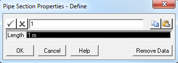
Component Properties |
Click on this button to display the properties of the Pipe Section, Cable, or Spring component that is currently selected. The dialog that is displayed shows the length of the pipe section, cable, or spring that is currently selected in the line stack-up. |
Duplicate |
Click on this button to create a copy of the entire stack-up. The dialog that is displayed allows the number of duplications required to be specified. |
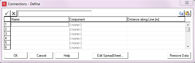
Connections |
Click on this button to display the Connections – Define dialog. See the ‘Connections – Define Dialog’ section for a detailed description of this dialog. |
Line Component Type |
A drop-down list that enables you to select the line component type. The options available are Standard, Payout and Active Length. The default is Standard. The Standard option meshes the Line component as normal. The Payout option specifies an initial length of pipe section which is meshed in the normal sense. The remaining section of the Line is meshed using “Inactive” elements, which are not yet included in the solution scheme. The “Inactive” elements are activated during subsequent pay out installation stages when additional pipeline is added. The Active Length option allows you to specify a region along the line which can actively change length during an analysis in accordance with relevant inputs. If you select Active Length, the Active Properties and Timetrace File buttons become enabled. See the ‘Active Properties Dialog’ and ‘Timetrace File Dialog’ for more information. Note that this drop-down list is disabled in PipeLay Starter Edition and the line component type is set to Standard. |
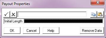
Payout Properties |
If you select Payout for the line component type, you can click on the Payout Properties button to specify the initial length. See the ‘Payout Properties Dialog’ for more information. |
Active Properties |
This button is enabled for the Active Length line component type only and it allows you to position the start of the active length region at a suitable distance along the line, to specify the initial length of the elements in the region as well as the initial length of the region itself, and finally to define the allowable length limits to be applied to the elements during subsequent line length change analyses. See the ‘Active Properties Dialog’ for more information. |
This button is enabled for the Active Length line component type only and it allows you to select an ASCII file containing a time history of line length change, via a standard Windows Open dialog. The time history in the file is applied to the active length region during a dynamic analysis in accordance with the procedure outlined in ‘Active Properties Dialog’. The expected format of the timetrace file consists of two columns of data. The first column contains time data while the second column contains the change in length with respect to the length prior to the dynamic analysis. Note that the change in length should be in either metres or feet depending on the unit system being used. Comment lines, denoted by a capital ‘C’ in the first column are permitted, while lines that are completely blank are ignored. Columns of data may be separated by commas, spaces or tabs. PipeLay uses cubic spline interpolation to find the change in length at time points between those specified in the timetrace file (for this reason the analysis timesteps do not need to match those in the timetrace file). Note that for analysis times before the earliest time specified in the length change timetrace file, PipeLay uses the values specified for the earliest time. Similarly, for analysis times after the latest time in the timetrace file, PipeLay uses the values specified for the latest time. |
Add Pipe Section Dialog |
Pipe Section properties define |
|
|
Input |
Description |
Section: |
A drop-down list that allows you to select a Pipe Section component from all those already defined in the project. The section to be added will be inserted into the line stack-up above the currently selected component. |
Length: |
The length of the pipe section to be added to the line stack-up. Units: [m] or [ft] |
Add Cable Dialog |
Cable properties Define |
|
|
Input |
Description |
Cable: |
A drop-down list that allows you to select a Cable component from all those already defined in the project. The cable to be added will be inserted into the line stack-up above the currently selected component. |
Length: |
The length of the cable to be added to the line stack-up. Units: [m] or [ft] |
Input |
Description |
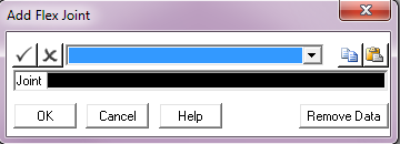
Joint: |
A drop-down list that allows you to select a Flex Joint component from all those already defined in the project. The flex joint to be added will be inserted into the line stack-up above the currently selected component. |
Input |
Description |
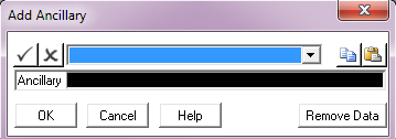
Ancillary: |
A drop-down list that allows you to select an Ancillary component from all those already defined in the project. The ancillary component to be added will be inserted into the line stack-up above the currently selected component. |
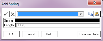
Add Spring Dialog |
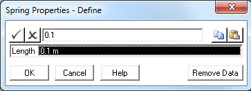
spring properties Define |
|
|
Input |
Description |
Spring: |
A drop-down list that allows you to select a Spring component from all those already defined in the project. The spring to be added will be inserted into the line stack-up above the currently selected component. |
Length: |
The length of the spring to be added to the line stack-up. The length you specify here is the initial length of the spring element used to model the spring in the finite element model. For most cases, the actual length you specify is not all that important – the force in the spring is proportional to the change in length of the spring element. However, you must specify a non-zero length, and it is usually beneficial to specify some finite length so that the line of action of spring will not vary continuously. The default length is 0.1, metres or feet, depending on the unit system employed in the project. Units: [m] or [ft] |
Input |
Description |
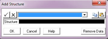
Structure: |
A drop-down list that allows you to select a Structure component from all those already defined in the project. The structure to be added will be inserted into the line stack-up above the currently selected component. |

Input |
Description |
Structure: |
A drop-down list that allows you to select a Tapered Stress Joint component from all those already defined in the project. The TSJ to be added will be inserted into the line stack-up above the currently selected component. |
Input |
Description |
Name: |
The name of the connection point. |
Component: |
A drop-down list that allows you to select a Connection component from those already defined in the project. The Connection component is only physically added to the line when another component such as a line, cable, or pipe section is actually connected to the line via the connection in the Model component. If when setting up the model no other component is connected to the line via the Connection component, then any specified properties are ignored. |
Distance along Line: |
The distance from the start of the line to the connection point. Units: [m] or [ft] |
Note:
Note that if you wish to apply a point load at some intermediate location along the line (i.e. not at either end), you must define a connection point at that location – even if you do not intend to connect anything at the point. This allows you to reference the required location along the line when associating a Load component with the line in the Parameters tab of the Analysis component.
Note
This dialog is not available in PipeLay Starter Edition
Input |
Description |
Initial Length: |
The initial length of the Line component. This input only applies to payout analyses. The payout option for Line components is based on having sufficient elements in the model at the first installation stage to be able to complete all subsequent payout installation stages without a requirement for generating new models. At the first installation stage to be analysed, the length of pipeline between the vessels may only be in the region of 500m. This is specified as the initial length. Therefore in the first installation stage, elements in the model between the range of 0 – 500m are deemed ‘active’ and included in the solution scheme. Elements outside this range are deemed ‘inactive’ and not included in the solution. ‘Inactive’ elements do not form part of the solution at any analysis stage and are only retained for element connectivity. In this way, pipe payout is modelled by switching ‘inactive’ elements to ‘active’, thereby adding the required extra length to the pipeline at each stage. At each analysis stage, it is possible to add a user-specified length of pipeline to the model. Using the approach specified above, ‘inactive’ elements corresponding to the additional length of pipeline to be added become ‘active’ and are included in the solution scheme. ‘Active’ elements for this analysis therefore include all ‘active’ elements from the previous analysis, in conjunction with those elements made ‘active’ by increasing the pipeline length. Boundary condition data is passed to the newly activated elements and the elements are then offset to the correct position. In this way, the correct catenary shape is reformulated. This method has the advantage of allowing the exact transfer of data between elements during a restart analysis, as element connectivity is retained from each installation stage. Using this approach, the GUI also only needs to generate a model for the first installation stage, based on the final length of pipeline, and does not need to regenerate a model for each subsequent analysis. A model with the final pipeline length is generated at the first installation stage and subsequent analyses restart from this, activating more elements at each stage as more pipeline length is deployed. It is important to note here that the final length of pipeline specified in the first analysis does not need to be the exact final length. However, the length must be of a significant magnitude to allow sufficient length of pipeline to be added at each payout installation stage. |
Note
This dialog is not available in PipeLay Starter Edition
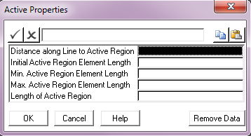
Input |
Description |
Distance along Line to Active Region |
The minimum distance from the start of the line to the start of the active region. This distance should be such that the active region does not fall within the extents of a specified stinger, touchdown region, or structure component. Units: [m] or [ft] |
Initial Active Region Element Length |
The initial element length inside the active region as applied by the user interface during model generation. This value must be less than the Max. Active Region Element Length and the Length of Active Region inputs. Units: [m] or [ft] |
Min. Active Region Element Length |
The smallest allowable length for an element in the active region. This limit is applied during a length change analysis where the requested change in length is negative. This value must be less than the Initial Active Region Element Length and the Max. Active Region Element Length inputs. Units: [m] or [ft] |
Max. Active Region Element Length |
The largest allowable length for an element in the active region. This limit is applied during a length change analysis where the requested change in length is positive. Units: [m] or [ft] |
Length of Active Region |
The minimum initial length of the active region as applied by the user interface during model generation. Elements inside this region have an initial length corresponding to the Initial Active Region Element Length input. This length should be such that the active region does not fall within the extents of a specified stinger, touchdown region, or structure component. Units: [m] or [ft] |
Note
This tab is not available in PipeLay Starter Edition
Input |
Description |
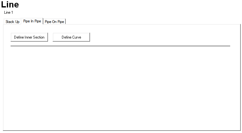
Define Inner Sections |
Click on this button to display the Pipe In Pipe Sections – Define dialog. See the ‘Pipe In Pipe Sections – Define Dialog’ section for a detailed description of this dialog. |
Define Curve |
Click on this button to display the Pipe In Pipe Contact Curve – Define dialog. See the ‘Pipe In Pipe Contact Curve – Define Dialog’ section for a detailed description of this dialog. |
Input |
Description |
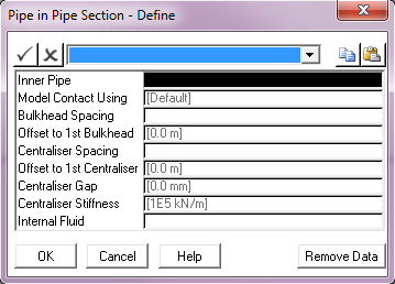
Inner Pipe: |
A drop-down list that allows you to select a Pipe Section component from those already defined in the project. You select the pipe section that you want to use as the inner pipe. For obvious reasons, the diameter of the inner pipe must be smaller than the outer pipe. |
Model Contact Using: |
A drop-down list that enables you to select the non-linear stiffness curve to model interaction between the inner pipe and the outer pipe. The options are Default or User Defined Curve. If you select Default, PipeLay determines the stiffness that is appropriate for the pipe interaction based on the other Pipe In Pipe values. If you select User Defined Curve, you must click on the Define Curve button in the Pipe In Pipe tab to define the stiffness curve. |
Bulkhead Spacing: |
The spacing between the bulkheads. Units: [m] or [ft] |
Offset to 1st Bulkhead: |
The distance from the start point of the pipeline to the first bulkhead. Units: [m] or [ft] |
Centraliser Spacing: |
The spacing between the centralisers. Units: [m] or [ft] |
Offset to 1st Centraliser: |
The distance from the start point of the pipeline to the first centraliser. Units: [m] or [ft] |
Centraliser Gap: |
The radial distance between the centralisers and the inner pipe. Units: [m] or [ft] |
Centraliser Stiffness: |
The linear stiffness of the centralisers. The default is 1E5 kN/m or kips/ft. Units: [kN/m] or [kips/ft] |
Internal Fluid: |
A drop-down list of all Internal Fluid components defined in the project. It is used to associate an internal fluid with the inner pipe. |
Input |
Description |
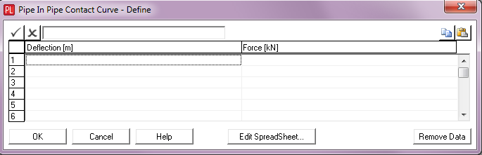
Deflection: |
A deflection value for a point on the contact curve. Units: [m] or [ft] |
Force: |
A force value that corresponds to the deflection value. Units: [kN] or [kips] |
Note
This tab is not available in PipeLay Starter Edition
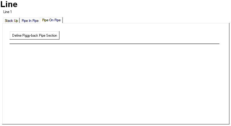
Input |
Description |
Define Piggy-back Pipe Section |
Click on this button to display the Pipe In Pipe Contact Curve – Define dialog. See the next section for a detailed description of this dialog. |

Input |
Description |
Piggy-back Pipe: |
A drop-down list that allows you to select a Pipe Section component from those already defined in the project. You select the pipe section that you want to use as the piggy-back pipe. |
X Offset: |
The vertical displacement of the centre of the piggy-back pipe relative to the centre of the main pipe. Units: [m] or [ft] |
Z Offset: |
The horizontal displacement of the centre of the piggy-back pipe relative to the centre of the main pipe. Units: [m] or [ft] |
Connection Spacing: |
The distance between the connections that support the piggy-back pipe on the main pipe. Units: [m] or [ft] |
Model Connection As: |
A drop-down list that allows you to select the pipe sliding behaviour of the model. The options available are Fixed or Interchangeable. The default is Fixed. If you select Fixed, PipeLay does not allow relative axial motion between the connections on the main pipe and the connections on the piggy-back pipe. If you select Interchangeable, PipeLay allows relative axial motion between the two pipes. With the Interchangeable option, if relative axial motion occurs, the connection on the piggy-back pipe can move to the next node to enable a sliding behaviour. |
Transverse Stiffness: |
The stiffness of the connections in the transverse direction. The default is 1E5 kN/m or kips/ft. Units: [kN/m] or [kips/ft] |
Axial Stiffness: |
The stiffness of the connections in the axial direction of the pipe. This value is only relevant if you select Interchangeable from the Model Connection As drop-down list. The default is 1E5 kN/m or kips/ft. Units: [kN/m] or [kips/ft] |
Internal Fluid: |
A drop-down list of all Internal Fluid components defined in the project. You use this list to associate an internal fluid with the piggy-back pipe. |