Stinger Section Data Inputs |


|
Stinger Section Data Inputs |
|
Input |
Description |
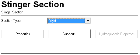
Section Type: |
A drop-down list that allows the selection of a stinger section type. The options are Rigid (the default), Flexible and Flexible Hydro. If you intend to use the stinger section to define a Hinged Rigid S-Lay stinger, you should select the Rigid option. In this case the stinger itself is not part of the finite element model, and the Stinger Section component is merely used to specify the initial locations of the rollerbox supports. You may choose the Flexible or Flexible Hydro options if you wish, but any structural and hydrodynamic properties that you specify will be superfluous to requirements and so will be ignored. If you intend to use the stinger section to define an Articulated S-Lay stinger, then you can select Rigid, Flexible or Flexible Hydro, depending on the information available to you. If you know the relevant stinger structural and hydrodynamic properties, you should select the Flexible or Flexible Hydro options and input these properties. Otherwise, you can select the Rigid format, and PipeLay will automatically compute default stinger properties for you. Note that the distinction between the Flexible and Flexible Hydro options is that the latter allows you to specify complex hydrodynamic properties for the stinger section to reflect the fact that they are arbitrary in shape and do not have a simple circular cross section. |
Properties |
Click on this button to display a dialog that allows you to enter the properties of the stinger section. The dialog that is displayed depends on the option that you selected in the Section Type drop-down list. See the ‘Stinger Section – Rigid Dialog’, ‘Stinger Section – Flexible Dialog’ and ‘Stinger Section – Flexible Hydro Dialog’ sections for more information. |
Supports |
Click on this button to display the Stinger Section Supports dialog. See the ‘Stinger Section Supports Dialog’ section in this article for a detailed description of this dialog. |
Hydrodynamic Properties |
Click on this button to display the Stinger Section – Hydrodynamic Properties dialog. See the ‘Stinger Section – Hydrodynamic Properties’ section in this article for a detailed description of this dialog. Note that this button only relates to the Flexible Hydro stinger section type and so is disabled for all other types. |
Input |
Description |
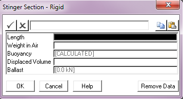
Length: |
The length of the stinger section. Units: [m] or [ft] |
Weight in Air: |
The weight in air or dry weight of the stinger section. Units: [kN] or [kips] |
Buoyancy: |
The buoyancy associated with the stinger section. This may be either a number or the word “CALCULATED”. The default is “CALCULATED” which means that the value of this input is computed internally by the user interface using the values you specify for the Displaced Volume of the stinger section and the Ballast of the section. However, you can override this computation, and input a value directly in this text box if you wish. Note that if the Displaced Volume input is omitted then the computed value corresponds to zero. Also note that the buoyancy value here, whether it is computed or specified, can be automatically optimised by subsequent Analysis components in order to achieve a set of stinger section orientations. This is discussed further in the Stinger component article. Units: [kN] or [kips] |
Displaced Volume: |
The volume of water displaced by the stinger section. This input is optional and is only used in the possible computation of stinger section Buoyancy. If omitted the internally computed buoyancy will be zero. Units: [m3] or [ft3] |
Ballast: |
The ballast of the stinger section. This input is only used in the possible computation of stinger section Buoyancy. Defaults to zero. Units: [kN] or [kips] |

Input |
Description |
Length: |
The length of the stinger section. Units: [m] or [ft] |
Bending Stiffness: |
The bending stiffness of the stinger section. Units: [kNm2] or [kips.ft2] |
Axial Stiffness: |
The axial stiffness of the stinger section. Units: [kN] or [kips] |
Torsional Stiffness: |
The torsional stiffness of the stinger section. Units: [kNm2 / radian] or [kips.ft2 / radian] |
Weight in Air: |
The weight in air or dry weight of the stinger section. Units: [kN] or [kips] |
Buoyancy: |
The buoyancy associated with the stinger section. This may be either a number or the word “CALCULATED”. The default is “CALCULATED” which means that the value of this input is computed internally by the user interface using the values you specify for the Displaced Volume of the stinger section and the Ballast of the section. However, you can override this computation, and input a value directly in this text box if you wish. Note that if the Displaced Volume input is omitted then the computed value corresponds to zero. Also note that the buoyancy value here, whether it is computed or specified, can be automatically optimised by subsequent Analysis components in order to achieve a set of stinger section orientations. This is discussed further in the Stinger component article. Units: [kN] or [kips] |
Displaced Volume: |
The volume of water displaced by the stinger section. This input is optional and is only used in the possible computation of stinger section Buoyancy. If omitted the internally computed buoyancy will be zero. Units: [m³] or [ft³] |
Ballast: |
The ballast of the stinger section. This input is only used in the possible computation of stinger section Buoyancy. Defaults to zero. Units: [kN] or [kips] |
Drag Diameter: |
The effective diameter for hydrodynamic force calculations for the stinger section. Units: [m] or [ft] |
Normal Drag: |
The Morison’s Eq. drag coefficient for the direction normal to the section, denoted |
Tangential Drag: |
The Morison’s Eq. drag coefficient for the direction tangential to the section, denoted |
Normal Inertia: |
The Morison’s Eq. inertia coefficient for the direction normal to the section, denoted |
Tangential Added Mass: |
The Morison’s Eq. added mass coefficient in the direction tangential to the section, denoted |
Normal Added Mass: |
The Morison’s Eq. added mass coefficient in the direction normal to the section, denoted |
Input |
Description |
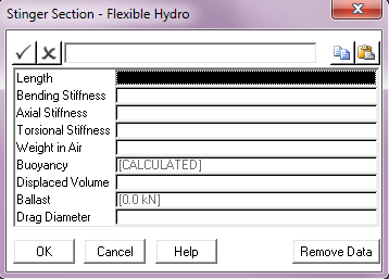
Length: |
The length of the stinger section. Units: [m] or [ft] |
Bending Stiffness: |
The bending stiffness of the stinger section. Units: [kNm2] or [kips.ft2] |
Axial Stiffness: |
The axial stiffness of the stinger section. Units: [kN] or [kips] |
Torsional Stiffness: |
The torsional stiffness of the stinger section. Units: [kNm2 / radian] or [kips.ft2 / radian] |
Weight in Air: |
The weight in air or dry weight of the stinger section. Units: [kN] or [kips] |
Buoyancy: |
The buoyancy associated with the stinger section. This may be either a number or the word “CALCULATED”. The default is “CALCULATED” which means that the value of this input is computed internally by the user interface using the values you specify for the Displaced Volume of the stinger section and the Ballast of the section. However, you can override this computation, and input a value directly in this text box if you wish. Note that if the Displaced Volume input is omitted then the computed value corresponds to zero. Also note that the buoyancy value here, whether it is computed or specified, can be automatically optimised by subsequent Analysis components in order to achieve a set of stinger section orientations. This is discussed further in the Stinger component article. Units: [kN] or [kips] |
Displaced Volume: |
The volume of water displaced by the stinger section. This input is optional and is only used in the possible computation of stinger section Buoyancy. If omitted the internally computed buoyancy will be zero. Units: [m³] or [ft³] |
Ballast: |
The ballast of the stinger section. This input is only used in the possible computation of stinger section Buoyancy. Defaults to zero. Units: [kN] or [kips] |
Drag Diameter: |
The diameter assigned to the stinger section for display purposes in any related animation files. Units: [m] or [ft] |
Input |
Description |
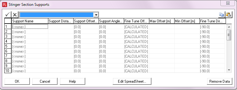
Support Name: |
A drop-down list which allows you to select a Support component from all those currently defined in the project. |
Support Distance: |
The distance to the support location from the upper end of the stinger section, measured parallel to the stinger section. See Note (a). Units: [m] or [ft] |
Support Offset: |
The perpendicular distance from the stinger section to the support location. The default is zero which is no offset. Units: [m] or [ft] |
Support Angle: |
The relative angle of the support, measured clockwise from the stinger section. A positive value corresponds to a positive rotation around the stinger z-axis. This input is optional and if omitted, an approximate orientation is automatically computed based on the adjacent support locations. Units: [degrees] |
Fine Tune Offset: |
The fine tune offset from the support location. This input is optional and defaults to [CALCULATED] if omitted. Calculated values are based on achieving the relevant Vessel – Radii of Curvature if defined. If a support does not fall within a Radii of Curvature region then the calculated fine tune offset is set to a zero value. Radii of Curvature are disabled in PipeLay Starter Edition. See Note (b). Units: [m] or [ft] |
Max. Offset: |
The maximum fine tune offset that can be applied to the support in reality. This input is optional and only relevant if Fine Tune Offset is set to [CALCULATED]. You can compare any calculated fine tune offset against the maximum value to see if it is feasible. See Note (b). Units: [m] of [ft] |
Min. Offset: |
The minimum fine tune offset that can be applied to the support in reality. This input is optional and only relevant if Fine Tune Offset is set to [CALCULATED]. You can compare any calculated fine tune offset against the minimum value to see if it is feasible. See Note (b). Units: [m] of [ft] |
Fine Tune Direction: |
The direction of the fine tune offset measured clockwise from the achieved support angle. A positive value corresponds to a positive rotation around the stinger z-axis. This input is optional and defaults to -90 degrees if omitted. Units: [degrees] |
Notes:
(a)Refer to the ‘Support’ article, specifically to the ‘Support Locations’ section, for a detailed description of the reference point on the support which corresponds to the support location input.
(b)Refer to Technical Note 8, ‘Calculation of Support Fine Tune Offsets’ for a detailed description of how the Fine Tune Offset is calculated.

Input |
Description |
Axis System: |
This drop-down list is used to select the axis system in which the hydrodynamic coefficients are defined. The options are Global (the default) and Local. The hydrodynamic coefficients can be specified in the global axis system or in an axis system that is local to the stinger section. In the latter case, the local x-axis of each element is used for the tangential force calculations, and the local y- and z-axes are used for the hydrodynamic forces normal to the section. Coefficients specified in either axis system account for changes in the orientation of the section as it displaces and rotates in space. Note that specification of stinger section hydrodynamic properties is optional. By default, section hydrodynamics will be omitted. |
X: CdAd: |
The product of the stinger section frontal area and drag coefficient in the X direction. Units: [m2] or [ft2] |
X: CmVin: |
The product of the stinger section reference volume and inertia coefficient in the X direction. Units: [m3] or [ft3] |
X: CaVin: |
The product of the stinger section reference volume and added mass coefficient in the X direction. Units: [m3] or [ft3] |
Y: CdAd: |
The product of the stinger section frontal area and drag coefficient in the Y direction. Units: [m2] or [ft2] |
Y: CmVin: |
The product of the stinger section reference volume and inertia coefficient in the Y direction. Units: [m3] or [ft3] |
Y: CaVin: |
The product of the stinger section reference volume and added mass coefficient in the Y direction. Units: [m3] or [ft3] |
Z: CdAd: |
The product of the stinger section frontal area and drag coefficient in the Z direction. Units: [m2] or [ft2] |
Z: CmVin: |
The product of the stinger section reference volume and inertia coefficient in the Z direction. Units: [m3] or [ft3] |
Z: CaVin: |
The product of the stinger section reference volume and added mass coefficient in the Z direction. Units: [m3] or [ft3] |