Stinger Data Inputs |


|
Stinger Data Inputs |
|
Overview
There are three types of Stinger component as follows:
•Rigid S-Lay stingers. These are configured in one of the following ways:
This article is divided into subsections corresponding to the Stinger configuration options listed above.

Stinger Component
Input |
Description |
Type: |
The stinger type. The options are Rigid S-Lay (the default), Articulated S-Lay and J-Lay. |
Configuration: |
The configuration type. This menu is only relevant when the stinger type is Rigid S-Lay, and is disabled otherwise. In this instance, the configuration options are Explicitly Defined (the default), Radius of Curvature Defined and Hinged. |
Support Locations |
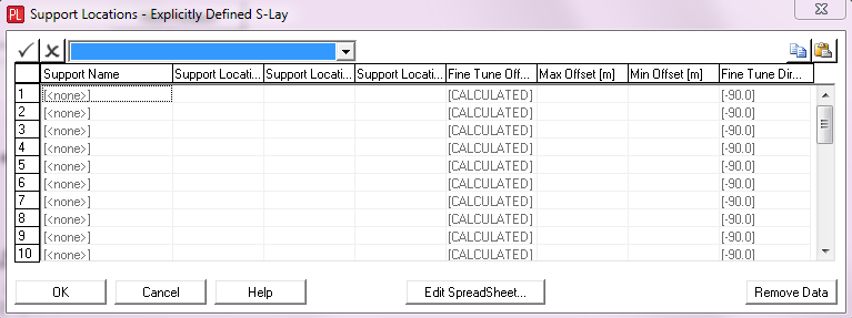
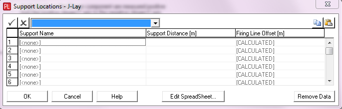
Click on this button to specify the support locations for a: •Rigid S-Lay stinger that is Explicitly Defined or Radius of Curvature Defined •J-Lay stinger |
Stinger Sections |
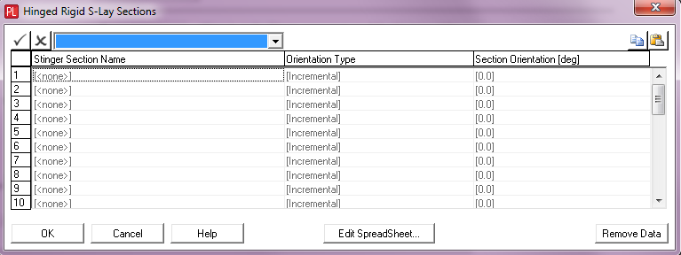
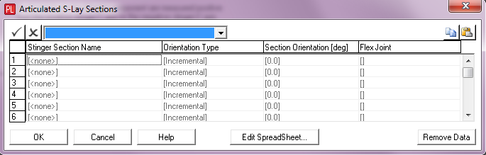
Click on this button to specify the stinger sections for a Hinged Rigid S-Lay or an Articulated S-Lay. |
Section Deformation |
Click on this button to define the undeformed orientation of the stinger sections/hinges |
Buoyancy |
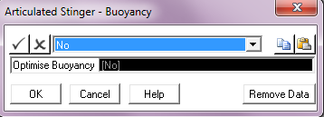
Click on this button to enable automatic buoyancy optimisation of the stinger sections on an Articulated S-Lay stinger. Note that this button is disabled in PipeLay Starter Edition. |
Centre of Curvature |
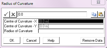
Click on this button to specify the centre of curvature for a Rigid S-Lay stinger that is Radius of Curvature Defined. |
Tower Properties |
Click on this button to specify the tower properties for a J-Lay stinger. |
Connection Point |
Click on this button to specify the connection points for a J-Lay stinger. |
Hitch Rotation |
Click on this button to specify the hitch rotation for all configuration types of Rigid S-Lay or Articulated S-Lay stingers. |
Input |
Description |
Support Name: |
A drop-down list which allows you to select a Support component from all those currently defined in the project. |
Support Location – X: |
The distance of the support location from the stinger origin measured along the stinger x-axis. The origin of the stinger axis system corresponds to the stinger origin specified on the Vessel component. The stinger x-axis corresponds to the vessel heave axis. The angle of the stinger y-axis relative to the vessel surge axis depends on the stinger angle specified on the vessel, which defaults to 180°, which is pointing in the aft direction. See Note (a). Units: [m] or [ft] |
Support Location – Y: |
The distance of the support location from the stinger origin measured along the stinger y-axis. See the description above for Support Location – X for more information. Units: [m] or [ft] |
Support Location – Angle: |
The angle of the support, measured clockwise from the stinger y-axis. A positive value corresponds to a positive rotation around the stinger z-axis. This input is optional and if omitted, an approximate orientation is automatically computed based on the adjacent support locations. Units: [degrees] |
Fine Tune Offset: |
The fine tune offset from the support location. This input is optional and defaults to [CALCULATED] if omitted. Calculated values are based on achieving the relevant Radii of Curvature as specified on the Vessel component. If a support does not fall within a Radii of Curvature region then the calculated fine tune offset is set to a zero value. Radii of Curvature are disabled in PipeLay Starter Edition. See Note (b). Units: [m] or [ft] |
Max. Offset: |
The maximum fine tune offset that can be applied to the support in reality. This input is optional and only relevant if Fine Tune Offset is set to [CALCULATED]. You can compare any calculated fine tune offset against the maximum value to see if it is feasible. See Note (b). Units: [m] of [ft] |
Min. Offset: |
The minimum fine tune offset that can be applied to the support in reality. This input is optional and only relevant if Fine Tune Offset is set to [CALCULATED]. You can compare any calculated fine tune offset against the minimum value to see if it is feasible. See Note (b). Units: [m] of [ft] |
Fine Tune Direction: |
The direction of the fine tune offset measured clockwise from the achieved support angle. A positive value corresponds to a positive rotation around the stinger z-axis. This input is optional and defaults to -90 degrees if omitted. Units: [degrees] |
Notes:
(a) Refer to the ‘Support’ article, specifically to the ‘Support Locations’ section, for a detailed description of the reference point on the support which corresponds to the support location input. Also, refer to the 'Stinger' article, in particular the 'Stinger Co-ordinate System' section, for an illustration of the stinger axis system.
(b) Refer to Technical Note 8, ‘Calculation of Support Fine Tune Offsets’, for a detailed description of how the Fine Tune Offset is calculated.
Input |
Description |
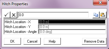
Hitch Location – X: |
The distance of the hitch location from the stinger origin measured along the stinger x-axis. The origin of the stinger axis system corresponds to the stinger origin specified on the Vessel component. The stinger x-axis corresponds to the vessel heave axis. The angle of the stinger y-axis relative to the vessel surge axis depends on the stinger angle specified on the vessel, which defaults to 180°, that is pointing in the aft direction. Refer to the 'Stinger' article, in particular the 'Stinger Co-ordinate System' section, for an illustration of the stinger axis system. Units: [m] or [ft] |
Hitch Location – Y: |
The distance of the hitch location from the stinger origin measured along the stinger y-axis. See the description above for Hitch Location – X for more information. Units: [m] or [ft] |
Hitch Location – Angle: |
The angle of the hitch, measured clockwise from the stinger y-axis. A positive value corresponds to a positive rotation around the stinger z-axis. This input is optional and defaults to zero if omitted. Units: [degrees] |
Input |
Description |
Centre of Curvature – X: |
The distance of the centre of curvature from the stinger origin measured along the stinger x-axis. The origin of the stinger axis system corresponds to the stinger origin specified on the Vessel component. The stinger x-axis corresponds to the vessel heave axis. The angle of the stinger y-axis relative to the vessel surge axis depends on the stinger angle specified on the vessel, which defaults to 180°, which is pointing in the aft direction. Refer to the 'Stinger' article, in particular the 'Stinger Co-ordinate System' section, for an illustration of the stinger axis system. Units: [m] or [ft] |
Centre of Curvature – Y: |
The distance of the centre of curvature from the stinger origin measured along the stinger Y-axis. See the description above for Centre of Curvature – X for more information. Units: [m] or [ft] |
Radius of Curvature: |
The radius of curvature of the stinger. Units: [m] or [ft] |
Input |
Description |
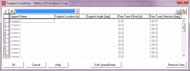
Support Name: |
A drop-down list which allows you to select a Support component from all those currently defined in the project. |
Support Location: |
The curvilinear distance of the support location from the top of the stinger. Note that this length is measured along the arc or radius from the top of the stinger, which is defined as being directly above the centre of curvature. See Note (a). Units: [m] or [ft] |
Support Angle: |
The angle of the support, measured clockwise from the stinger y-axis. A positive value corresponds to a positive rotation around the stinger z-axis. This input is optional and if omitted, the support is aligned with a tangent vector to the stinger profile at that location. Units: [degrees] |
Fine Tune Offset: |
The fine tune offset from the support location. This input is optional and defaults to zero if omitted. Units: [m] or [ft] |
Fine Tune Direction: |
The direction of the fine tune offset measured clockwise from the achieved support angle. A positive value corresponds to a positive rotation around the stinger z-axis. This input is optional and defaults to -90 degrees if omitted. Units: [degrees] |
Notes:
| (a) | Refer to the ‘Support’ article, specifically to the ‘Support Locations’ section, for a detailed description of the reference point on the support which corresponds to the support location input. Also, refer to the 'Stinger' article, in particular the 'Stinger Co-ordinate System' section, for an illustration of the stinger axis system. |
Hitch Properties Dialog
For a detailed description of the Hitch Properties dialog, see previous section under Explicitly Defined Rigid S-lay.
Input |
Description |
Stinger Section Name: |
A drop-down list which allows you to select a Stinger Section component from all those currently defined in the project. The stinger sections should be specified in order from vessel to tip. The orientation of each section may be specified as an absolute angle with respect to the horizontal plane or as an incremental angle relative to the previous section. |
Orientation Type: |
A drop-down list which allows you to select the orientation type. The options are Incremental (the default) and Absolute. |
Section Orientation: |
The angle of the stinger section. Units: [degrees] |
Flex Joint: |
A drop-down list which allows you to select a Flex Joint component from all those currently defined in the project. If no Flex Joint is selected here, PipeLay will create a default rigid connection between the section in question and the previous section on the stinger. When a Flex Joint is specified to use a non-linear moment-angle curve for rotational stiffness then it is worth noting that a downward rotation of the joint generally corresponds to a negative angle on the curve, whereas an upward rotation corresponds to a positive angle. This convention may influence how you define the moment-angle curve for the Flex Joint. |

Input |
Description |
Undeformed Orientation: |
A drop-down list that you use to specify the Undeformed Orientation for stinger sections/hinges as being either aligned with the Horizontal plane or with the Specified Orientation under the Articulated S-Lay Sections dialog. Selecting Horizontal means that the origin point (zero rotation point) for the moment-angle curve of any flex joint along the stinger corresponds to the flex joint being perfectly aligned with the horizontal plane. On the other hand, selecting Specified Orientation means that the origin for the flex joint moment-angle curve corresponds to the flex joint being aligned with the individual Section Orientation specified under the Articulated S-Lay Sections dialog. The latter option means that if you change the Section Orientation at any point then you may also have to change the flex joint curve so as maintain the same overall global rotational response, which is controlled in reality by hinge rotation stops etc. Clearly the Horizontal option does not encounter such an issue as the curve origin is always fixed regardless of the Section Orientation. |
Note
The automatic optimisation of stinger section buoyancy is disabled in PipeLay Starter Edition. Also, this capability is not fully compatible for use with the Horizontal Undeformed Orientation option and so the use of both in tandem should be avoided.
Input |
Description |
Optimise Buoyancy: |
A drop-down which allows you to request optimisation of stinger section buoyancy. The options are No (the default) and Yes. Selecting Yes in the drop-down forces PipeLay to automatically optimise the buoyancy of each stinger section so as to statically maintain the section orientations specified in the Articulated S-Lay Sections dialog. This optimisation process is carried out during a static analysis of any model containing the stinger. See Note (a). |
Notes:
(a) Refer to ‘Stinger’, specifically to the ‘Articulated S-Lay Stinger’ section, for a detailed description of this option.
For a detailed description of the Hitch Properties dialog, see previous section under Explicitly Defined Rigid S-lay.
Input |
Description |
Support Name: |
A drop-down list which allows you to select a Support component from all those currently defined in the project. |
Support Distance: |
The distance from the support location to the stinger origin, measured along the tower. See Note (a). Units: [m] or [ft] |
Firing Line Offset: |
The perpendicular distance from the centreline of the J-Lay tower to the support location. This may be either a number or the word “CALCULATED”. The default is “CALCULATED” which means that the value of this input is computed internally such that the support is centred about the firing line, or in other words the pipeline running through the support is automatically kept collinear with the firing line. However, you can override this computation, and input a value directly in this text box. Units: [m] or [ft] |
Notes:
| (a) | Refer to the ‘Support’ article, specifically to the ‘Support Locations’ section, for a detailed description of the reference point on the support which corresponds to the support location input. Also, refer to the 'J-Lay Tower' article for an illustration of the tower system. |
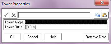
Input |
Description |
Tower Angle: |
The orientation of the tower, measured anti-clockwise from the stinger y-axis. The origin of the stinger axis system corresponds to the stinger origin specified on the Vessel component. The stinger x-axis corresponds to the vessel heave axis. The angle of the stinger y-axis relative to the vessel surge axis depends on the stinger angle specified on the vessel, which defaults to 180°, which is pointing in the aft direction. Refer to the 'Stinger' article, in particular the 'Stinger Co-ordinate System' section, for an illustration of the stinger axis system. Also, refer to the 'J-Lay Tower' article for an illustration of the tower system. Units: [degrees] |
Tower Offset: |
The perpendicular distance from the centreline of the J-Lay tower to the tower hinge point. This input is optional and defaults to zero if omitted. Units: [m] or [ft] |
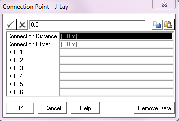
Input |
Description |
Connection Distance: |
The distance of the connection point from the stinger origin measured along the J-Lay tower. |
Connection Offset: |
The perpendicular distance from the centreline of the J-Lay tower to the connection point. |
DOF 1: |
The nature of the constraint provided in degree of freedom (DOF) 1. See Notes (a) to (c) below. |
DOF 2: |
The nature of the constraint provided in DOF 2. See Notes (a) to (c) below. |
DOF 3: |
The nature of the constraint provided in DOF 3. See Notes (a) to (c) below. |
DOF 4: |
The nature of the constraint provided in DOF 4. See Notes (a) to (c) below. |
DOF 5: |
The nature of the constraint provided in DOF 5. See Notes (a) to (c) below. |
DOF 6: |
The nature of the constraint provided in DOF 6. See Notes (a) to (c) below. |
Notes:
a)The nature of the constraint provided is governed by the DOF 1-DOF 6 inputs. For example, a pinned constraint may be modelled by inputting zero in the first three boxes. Setting all terms to zero is appropriate for built-in connections. Note that you must type in a zero in each degree of freedom which you wish to constrain – if you leave any inputs blank, no constraint are applied in those degrees of freedom. You may also input non-zero displacements – in which case constraints are applied and the relevant displacements are applied as static offsets.
b)It is important if specifying displacements in DOFs 4-6 to understand the significance of these degrees of freedom. You will no doubt be aware that finite (non-infinitesimal) 3D rotations cannot be represented as vectors, since the addition of such vectors is non-commutative, that is, the order in which the rotations are taken affects the result. In PipeLay this problem is handled by means of a consistent 3D kinematics formulation based on the correspondence between a specially defined rotation vector and a transformation matrix. Manipulation of the rotation is undertaken by means of operations on the transformation matrices. (You will note that as required matrix multiplication is non-commutative.)
The cornerstone of this formulation is the definition of the rotation vector referred to above. The full details are omitted here, but, in summary, a rotation is represented by a vector such that i) the magnitude of the vector represents the magnitude of the rotation, and ii) the direction of the vector represents the axis of rotation. Therefore the inputs for DOFs 4-6 are the components of this rotation vector. It is particularly important to realise that in general they do not represent individual rotations about the global coordinate X, Y and Z axes.
c)Although it is important to be aware of the foregoing in general, in many cases the situation is somewhat simplified. Firstly, in an analysis where the structure remains throughout in either the XY, XZ or the YZ plane (that is, in a 2D analysis), obviously there is only one rotation component active (for example, DOF 6 if the structure is in the vertical XY plane). In this case, the significance of the displacement is obvious and represents a rotation about the appropriate global axis (the global Z for the structure in the XY plane). Similarly, in a 3D analysis, the individual displacements will represent individual displacements about the global axes if the overall rotation is 'small', say less than 10°.
| However, in the general 3D case where large rotations are predicted, this is not the case, and the above definition of the rotation components is valid. In practice, this means you should be wary of specifying only 1 or 2 rotation components (that is, 1 or 2 only of DOFs 4-6) in an analysis with large rotations, and you should only do so if you understand exactly the effect of what you are doing. |