Vessel Data Inputs |


|
Vessel Data Inputs |
|
Input |
Description |
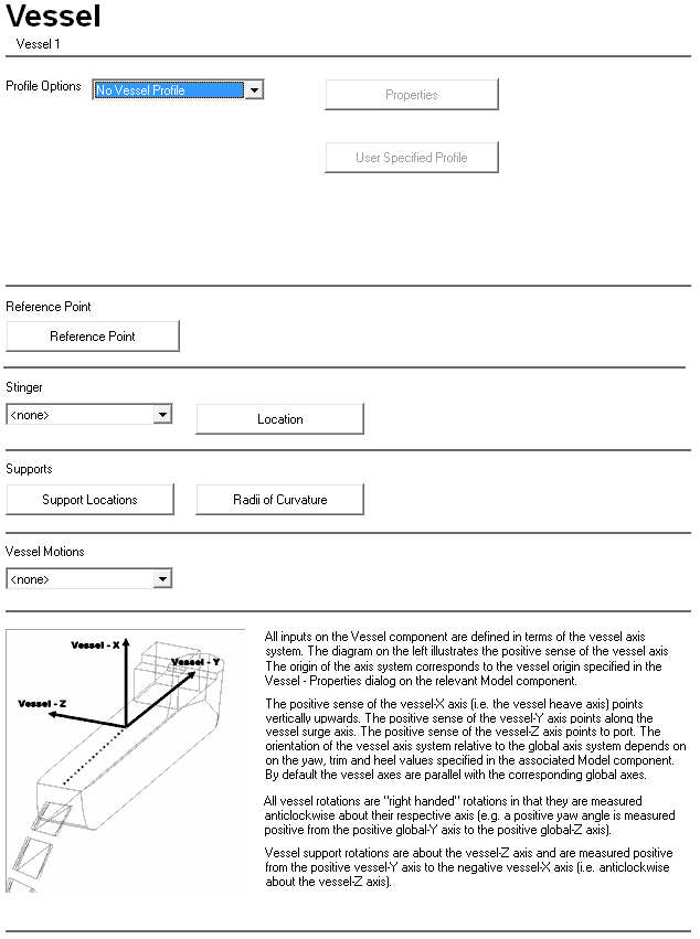
Profile Options: |
This drop-down list allows you to choose whether or not a vessel profile is to be included in any model views or dynamic display files generated for models that include this component. If the vessel profile is to be included, three profile options are available. By default, no vessel profile is generated. |
Properties |
This button is only available if you select Standard Vessel Profile, TLP Vessel Profile, or User Vessel Profile from the Profile Options drop-down list. The properties dialog that is displayed varies depending on the option that you select. See the ‘Standard Vessel – Properties Dialog’, ‘TLP Profile Properties – Define Dialog’ or ‘Standard Vessel – User Profile Properties Dialog’ sections in this article for more information. |
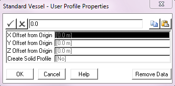
User Specified Profile |
When you click on this button, a standard Windows Open dialog is displayed prompting you to enter the name of an ASCII data file containing the vessel profile. If the User Vessel Profile option is selected, then a vessel profile you define explicitly is in the model view and dynamic display files generated for any model that includes the Vessel component. Again this is purely for illustrative purposes. The vessel profile is contained in an ASCII file and is input as a series of point locations, connections and panels. The file has four sections, delineated by lines with the words COORDINATES, CONNECTIONS, PANELS and PANELCOLOURS. In the COORDINATES section you list point coordinates defined relative to the vessel reference point. In the CONNECTIONS section you simply specify which points are connected to which, by listing the two connected points on a line. In the PANELS section you specify triangular panels between three listed points coordinates. Finally in the PANELCOLOURS section you assign hex colour codes to the defined panels. Note that the PANELS and PANELCOLOURS sections are only relevant when a solid vessel profile is requested. The format of a sample profile file with only four points joined by four connection and two panels would be as follows: COORDINATES 1, 0, 10, 10 2, 0, 10, -10 3, 0, -10, -10 4, 0, -10, 10 CONNECTIONS 1, 2 2, 3 3, 4 4, 1 PANELS 1, 1, 2, 3 2, 3, 4, 1 PANELCOLOURS 1,2, FF0000 |
Reference Point |
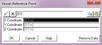
Click on this button to open the Vessel Reference Point dialog. By default, the location of the vessel reference point is the same as the vessel origin. The vessel reference point is the point on the vessel for which vessel RAOs and motions are defined. See the ‘Vessel Reference Point Dialog’ section in this article for more information. |
Stinger: |
A drop-down list that allows the selection of a Stinger component from all those already defined in the project. |
Location |
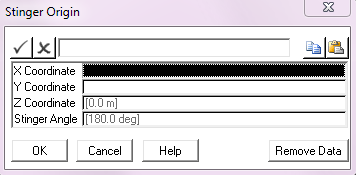
Click on this button to open the Stinger Origin dialog. See the ‘Stinger Origin Dialog’ section in this article for more information. |
Support Locations |
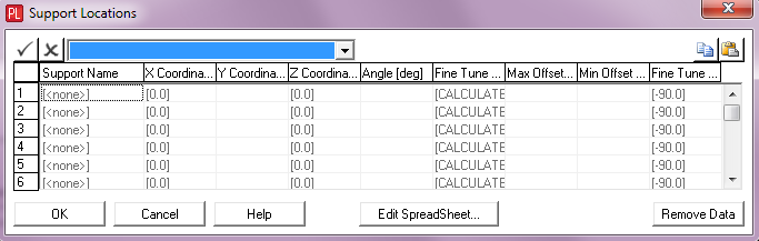
Click on this button to open the Support Locations dialog. See the ‘Support Locations Dialog’ section in this article for more information. |
Vessel Motions: |
A drop-down list that allows you to select a Vessel Motion component from all those currently defined in the project. |
Standard Vessel – Properties Dialog
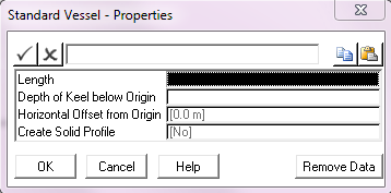
If the Standard Vessel Profile is selected, then an outline of a generic vessel is included in the model view and dynamic display files generated for any model that includes this Vessel component. PipeLay generates a typical vessel profile based on overall dimensions you specify. This facility is purely for illustrative purposes and has no effect on the analysis results.
Input |
Description |
Length: |
The length of the vessel. This determines the scaling of the vessel profile. Units: [m] or [ft] |
Depth of Keel below Origin: |
The vertical distance from the vessel origin to the vessel keel. This determines the height in the water of the vessel profile. Units: [m] or [ft] |
Horizontal Offset from Origin: |
The distance from the vessel origin to the midpoint of the vessel profile in the local vessel surge direction. This determines the positioning of the profile relative to the vessel origin. This value defaults to 0. Units: [m] or [ft] |
Create Solid Profile: |
A drop-down list that allows you to select whether you want a solid vessel profile to be created in subsequent analysis animations or not. The values are either Yes or No (default). |
TLP Profile Properties – Define Dialog
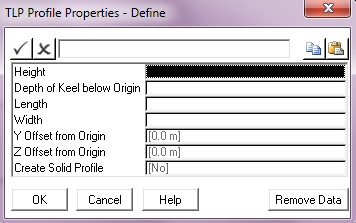
If the TLP Vessel Profile is selected, then an outline of a TLP is included in the model view and dynamic display files generated for any model that includes the Vessel component. PipeLay generates a typical vessel profile based on overall dimensions you specify. This facility is purely for illustrative purposes and has no effect on the analysis results.
Input |
Description |
Height: |
The total height of the TLP, from keel to deck. This determines the scaling of the vessel profile. Units: [m] or [ft] |
Depth of Keel below Origin: |
The vertical distance from the vessel origin to the TLP keel. This determines the height in the water of the vessel profile. Units: [m] or [ft] |
Length: |
The length of the TLP (corresponding to the local surge direction). Units: [m] or [ft] |
Width: |
The width of the TLP (corresponding to the local sway direction). Units: [m] or [ft] |
Y Offset from Origin: |
The distance from the vessel origin to the midpoint of the vessel profile in the local vessel surge direction. This input, in conjunction with Z Offset, determines the horizontal location of the vessel profile relative to the vessel origin. This value defaults to zero. Units: [m] or [ft] |
Z Offset from Origin: |
The distance from the vessel origin to the midpoint of the vessel profile in the local vessel sway direction. This input, in conjunction with Y Offset, determines the horizontal location of the vessel profile relative to the vessel origin. This value defaults to zero. Units: [m] or [ft] |
Create Solid Profile: |
A drop-down list that allows you to select whether you want a solid vessel profile to be created in subsequent analysis animations or not. The values are either Yes or No (default). |
Input |
Description |
X Offset from Origin: |
The distance from the vessel origin to the midpoint of the vessel profile in the local vessel heave direction. This input, in conjunction with Y Offset & Z Offset, determines the location of the vessel profile relative to the vessel origin. This value defaults to zero. Units: [m] or [ft] |
Y Offset from Origin: |
The distance from the vessel origin to the midpoint of the vessel profile in the local vessel surge direction. This input, in conjunction with X Offset & Z Offset, determines the location of the vessel profile relative to the vessel origin. This value defaults to zero. Units: [m] or [ft] |
Z Offset from Origin: |
The distance from the vessel origin to the midpoint of the vessel profile in the local vessel sway direction. This input, in conjunction with X Offset & Y Offset, determines the location of the vessel profile relative to the vessel origin. This value defaults to zero. Units: [m] or [ft] |
Create Solid Profile: |
A drop-down list that allows you to select whether you want a solid vessel profile to be created in subsequent analysis animations or not. The values are either Yes or No (default). |
Input |
Description |
X Coordinate: |
The distance of the vessel reference point from the vessel origin in the local vessel heave direction. This value defaults to 0.0. Units: [m] or [ft] |
Y Coordinate: |
The distance of the vessel reference point from the vessel origin in the local vessel surge direction. This value defaults to 0.0. Units: [m] or [ft] |
Z Coordinate: |
The distance of the vessel reference point from the vessel origin in the local vessel sway direction. This value defaults to 0.0. Units: [m] or [ft] |
Input |
Description |
X Coordinate: |
The distance of the stinger origin location from the vessel origin in the local vessel heave direction. Units: [m] or [ft] |
Y Coordinate: |
The distance of the stinger origin location from the vessel origin in the local vessel surge direction. Units: [m] or [ft] |
Z Coordinate: |
The distance of the stinger origin location from the vessel origin in the local vessel sway direction. This value defaults to zero. Units: [m] or [ft] |
Stinger Angle: |
The angle between the stinger y-axis and the local vessel surge axis. This value defaults to 180º (i.e. pointing in the aft direction). Units: [degrees] |
Input |
Description |
Support Name: |
A drop-down list which allows you to select a Support component from all those currently defined in the project. |
X Coordinate: |
The distance of the support location from the vessel origin measured along the local vessel heave axis. See Note (a). Units: [m] or [ft] |
Y Coordinate: |
The distance of the support location from the vessel origin measured along the local vessel surge axis. Units: [m] or [ft] |
Z Coordinate: |
The distance of the support location from the vessel origin measured along the local vessel sway axis. Units: [m] or [ft] |
Angle: |
The angle of the support, measured anti-clockwise from the local vessel surge axis. This input is optional and if omitted, an approximate orientation is automatically computed based on the adjacent support locations. Units: [degrees] |
Fine Tune Offset: |
The fine tune offset from the support location. This input is optional and defaults to [CALCULATED] if omitted. Calculated values are based on achieving the relevant Radii of Curvature as specified in the associated dialog. If a support does not fall within a Radii of Curvature region then the calculated fine tune offset is set to a zero value. Radii of Curvature are disabled in PipeLay Starter Edition. See Note (b). Units: [m] or [ft] |
Max. Offset: |
The maximum fine tune offset that can be applied to the support in reality. This input is optional and only relevant if Fine Tune Offset is set to [CALCULATED]. You can compare any calculated fine tune offset against the maximum value to see if it is feasible. See Note (b). Units: [m] or [ft] |
Min. Offset: |
The minimum fine tune offset that can be applied to the support in reality. This input is optional and only relevant if Fine Tune Offset is set to [CALCULATED]. You can compare any calculated fine tune offset against the minimum value to see if it is feasible. See Note (b). Units: [m] or [ft] |
Fine Tune Direction: |
The direction of the fine tune offset with respect to the support angle. This input is optional and defaults to -90 degrees if omitted. Units: [degrees] |
Notes:
(a)Refer to the ‘Support’ article, specifically to the ‘Support Locations’ section, for a detailed description of the reference point on the support which corresponds to the support location input.
(b)Refer to Technical Note 8, ‘Calculation of Support Fine Tune Offsets’ for a detailed description of how the Fine Tune Offset is calculated.
Note
This dialog is not available in PipeLay Starter Edition
Input |
Description |
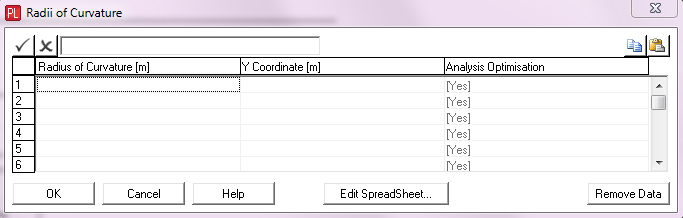
Radius of Curvature: |
The radius of curvature that is to apply to supports on the stern side of the corresponding Y Coordinate. This must be a positive non-zero entry. If a support is in a region of curvature and has its Fine Tune Offset set to [CALCULATED] then the PipeLay user interface offsets the support location so that it falls on the desired arc of curvature. See Note (a). Units: [m] or [ft] |
Y Coordinate: |
The distance of the tangent point between two areas of different pipe curvature from the vessel origin measured along the local vessel surge axis. A Y Coordinate input is mandatory for each specified Radius of Curvature. For multiple Radii of Curvature, the coordinates are to be in descending order. Units: [m] or [ft] |
Analysis Optimisation: |
A drop-down list which allows you to select Yes or No to instruct the analysis engine to carry out further optimisation on the Fine Tune Offset for supports in the corresponding area of curvature. Such additional optimisation may be needed when there are concentrations of curvature over supports. See Note (a). |
Notes:
(a)Refer to Technical Note 8, ‘Calculation of Support Fine Tune Offsets’ for a detailed description of how the Fine Tune Offset is calculated by the user interface and optimised by the analysis engine.