Model Best Practice |


|
Model Best Practice |
|
Validation of models is an important step to a successful analysis. This generally requires the following checks:
1.Confirm that the connection points have suitable boundary conditions. While a line may appear to be restrained when you connect it to a connection point, it is not restrained in an analysis without boundary conditions being specified. Boundary conditions in DOF1-3 and DOF4-5 should typically be set to zero for models specified in the global X-Y plane. Conditions in DOF1-3 are not needed for connection points at tensioners as the tensioner and its corresponding support component provide translation restraint to the line.


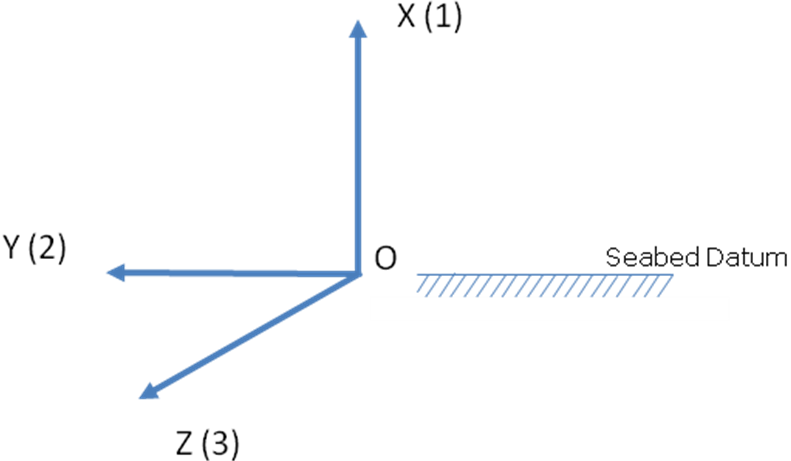

2.Review line lengths and distances between start/end points of a line. Convergence issues are often caused by excessive deformation or global buckling behaviour in the static analysis. Therefore, ensure no stretching or excessive curvature in the model, particularly for the sag-bend. This can be done by checking that the departure angle of the line as it leaves the stinger is less than or equal to the stinger tip angle. Note that for shallow water models where the tip is close to the seabed then you may have to look at reducing the departure angle further so as to ensure sufficient tip separation for the sag-bend. The following figures illustrate the previous points.

3.Calculated seabed connection points automatically try to achieve a suitable line profile taking into account the previous points with regards to pipeline stinger departure. Therefore, for efficiency it is best to use seabed connections as much as possible. However, the calculated points may not always be ideal so a review of the provided line profile is important. If you are not satisfied with the line profile, you can manually move the calculated point (generally any required movements are small). Shallow water models are particularly sensitive with fine margins between a stable model (leading to successful convergence) and a problematic model (leading to convergence errors).
4.Avoid having excessive lengths of line on the seabed (particularly if the seabed is flat) as this results in extra unneeded elements and longer run times. Refer to the previous 'Line Best Practice' article for guidance on ideal line lengths.
5.In a similar vain to point 3, use automatic vessel connection points as well rather than having to manually position connection points by yourself. This improves the ease of use for the Model component. Remember that the general goal when using the Model component is to set-up models in a relatively quick arbitrary fashion and then use the criteria analysis capability to automatically optimise them to the desired configuration. Refer to the Analysis component article for more information on criteria analysis.
6.If you wish to assess large static vessel yaw or roll rotations relative to the plane/axis of the pipeline then it is best to apply them as vessel offsets in a restart analysis rather than including them directly in the model. The reason for this is that the Model component does not realistically capture out of plane bending or torsional behaviour and so analysis convergence may prove difficult if the relative rotation values are high in the model. It is better suited to apply such rotations incrementally during a restart analysis. Refer to the Analysis Component article from more details on restart analyses.
7.For scenarios where there are considerable changes in contact diameter across the vessel/stinger supports, for example where there are flanges or tapering of pipe sections, it is best to change the Solver Contact Diameter option on the Advanced Options dialog. By default, this option is set to Individual meaning that each individual section diameter across the line is accounted for when determining where to position model nodes over supports. This can result in sudden jumps in the model line profile over supports where there is a change in contact diameter (Model component fixes each node at a specific elevation based on diameter) and these jumps can in turn cause inaccurate line lengths in the actual analysis as well as convergence difficulties. With this in mind, the model Solver Contact Diameter option should be set to one of the other values (Average, Weighted Average, Minimum or Maximum), which use a single uniform contact diameter across the entire line model and so keep the model support nodes at a constant elevation regardless of individual section diameters. The Minimum diameter value is typically the best to use as the analysis engine finds it easier to push nodes upwards from a minimum elevation during the initial static analysis. Note that the discussion of contact diameter here relates to the Model component only (initial positioning) as during the actual analysis each section diameter is automatically captured in the solution.
