Fatigue Tab |


|
Fatigue Tab |
|
Note
Fatigue postprocessing in not available in PipeLay Starter Edition
All parameters relating to fatigue life computations are specified on the Fatigue tab of the Analysis component. Three options are provided for calculating fatigue damage during pipe laying operations. The first is used to determine the damage sustained during normal lay operations. The second is employed to calculate the damage sustained during operations which are analysed as a series of sequential steps, such as abandonment or recovery. The third and final option is similar to the second, but it also adopts some traits from the first approach. User inputs include selection of installation type (normal lay, staged or hybrid staged), selection of the Line/Pipe Section component of interest, specification of weld locations, and specification of weld fatigue properties (SCFs, S-N Curves etc.). Outputs include total fatigue damage and standby time (maximum time the suspended pipe can be held stationary without sustaining excessive fatigue damage). Damage rate as a function of pipeline length is also output in graphical format.
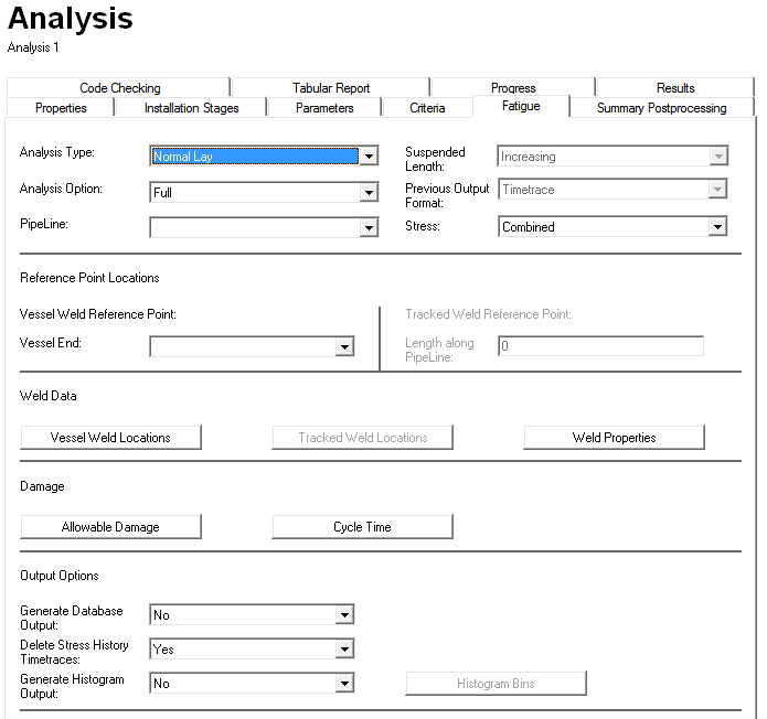
The layout of the Fatigue tab in the Analysis component is shown in the figure above and the inputs are divided into five main categories, as follows:
▪The Fatigue Analysis Options section at the top allows you to define your fatigue analysis type; to specify the pipe section of interest in your model; and to indicate if you wish to run a full dynamic random sea analysis prior to the fatigue calculations, or to use results from a dynamic analysis already run.
▪The Reference Point Locations section allows you to specify certain reference points to be used in the designation of weld locations.
▪The Weld Data section allows you to specify the locations of welds (fatigue hot spots) and to associate fatigue properties with these welds, such as S-N curves and SCFs.
▪The Damage section allows you to specify the allowable fatigue damage and the cycle time.
▪The Output Options section provides you with control over the level of generated output. Should you wish to generate histogram outputs, you can specify the stress bins in the Histogram Bins dialog.
The Normal Lay, Staged Operations and Hybrid Staged Operations fatigue options are now described in separate articles as follows:
▪‘Fatigue - Normal Lay - User Inputs’ describes the relevant inputs of a Normal Lay fatigue analysis.
▪‘Fatigue - Normal Lay - Operation’ describes the general operation of a Normal Lay fatigue analysis.
▪‘Fatigue - Normal Lay - Outputs’ describes the outputs of a Normal Lay fatigue analysis.
▪‘Fatigue - Staged Operations - User Inputs’ describes the relevant inputs for a Staged Operations fatigue analysis.
▪‘Fatigue - Staged Operations - Operation’ describes how PipeLay performs a Staged Operations fatigue analysis.
▪‘Fatigue - Staged Operations - Outputs’ describes the outputs of a Staged Operations fatigue analysis.
▪‘Fatigue - Hybrid Staged Operations - User Inputs’ describes the relevant inputs of a Hybrid version of the Staged Operations fatigue analysis.
▪‘Fatigue - Hybrid Staged Operations - Operation & Outputs’ describes the general operation of a Hybrid version of the Staged Operations fatigue analysis and the relevant outputs.
An additional article provides information on the Fatigue Tab Best Practice.