Structure Data Inputs |


|
Structure Data Inputs |
|
Note
This component is not available in PipeLay Starter Edition
Input |
Description |
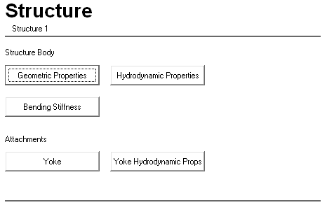
Geometric Properties |
Click on this button to display the Structure – Properties dialog. See the ‘Structure – Properties Dialog’ section in this article for more information. |
Hydro-dynamic Properties |
Click on this button to display the Structure – Hydrodynamic Properties dialog. See the ‘Structure – Hydrodynamic Properties Dialog’ section in this article for more information. |
Bending Stiffness |
Click on this button to display the Structure – Bending Stiffness dialog. See the ‘Structure – Bending Stiffness Dialog’ section in this article for more information. |
Yoke |
Click on this button to display the Yoke – Properties dialog. See the ‘Yoke – Properties Dialog’ section in this article for more information. |
Yoke Hydro-dynamic Props |
Click on this button to display the Yoke – Hydrodynamic Properties dialog. See the ‘Yoke – Hydrodynamic Properties Dialog’ section in this article for more information. |
Input |
Description |
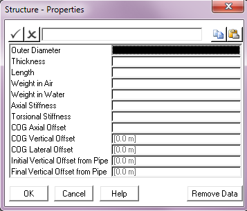
Outer Diameter: |
The outer diameter of the structure. Units: [mm] or [in] |
Thickness: |
The wall thickness of the structure. Units: [mm] or [in] |
Length: |
The length of the structure. Units: [m] or [ft] |
Weight in Air: |
The weight in air or dry weight of the structure. Units: [kN] or [kips] |
Weight in Water: |
The weight in water or submerged weight of the structure. Units: [kN] or [kips] |
Axial Stiffness: |
The axial stiffness of the structure. Units: [kN] or [kips] |
Torsional Stiffness: |
The torsional stiffness of the structure. Units: [kNm2/rad] or [kips.ft2/rad] |
COG Axial Offset: |
The distance along the structure centreline from its start point to the point where the centre of gravity element connects to the structure. By default, this input is left blank in which case the structure weight is uniformly distributed along its length. Units: [m] or [ft] |
COG Vertical Offset: |
The in-plane displacement of the centre of gravity node with respect to the structure centreline (that is, the perpendicular distance from the structure centreline to the free end of the centre of gravity element as measured in elevation view). This defaults to 0. See Note (a). Units: [m] or [ft] |
COG Lateral Offset: |
The horizontal distance between the structure centreline and the centre of gravity node as measured in side view (that is, the out-of-plane displacement for the centre of gravity node). This defaults to 0. See Note (b). Units: [m] or [ft] |
Initial Vertical Offset from Pipe: |
The in-plane displacement of the structure start point with respect to the pipe centreline (that is, the perpendicular distance from the pipe centreline to the structure start point as measured in the elevation view). This defaults to 0. See Note (c).
Units: [m] or [ft] |
Final Vertical Offset from Pipe: |
The in-plane displacement of the structure end point with respect to the pipe centreline (that is, the perpendicular distance from the pipe centreline to the structure end point as measured in the elevation view). This defaults to 0. See Note (c). Units: [m] or [ft] |
Notes:
(a)If the line on which the structure is located has a start point with a smaller global Y coordinate than the end point then a positive COG Vertical Offset will place the COG node above the structure centreline. The opposite is true if the line start point has a larger Y coordinate.
(b)If the main pipeline is completely defined in the global XY plane (generally the case) a positive COG Lateral Offset will be measured along the positive global Z axis.
(c)The vertical offsets from pipe follow the same sign convention as the COG Vertical Offset.
Input |
Description |
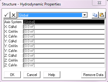
Axis System: |
This drop-down list is used to select the axis system in which the hydrodynamic coefficients are defined. The options are Global (the default) and Local. The hydrodynamic coefficients can be specified in the global axis system or in an axis system that is local to the structure. In the latter case, the local x-axis of each element is used for the tangential force calculations, and the local y- and z-axes are used for the hydrodynamic forces normal to the structure. Coefficients specified in either axis system account for changes in the orientation of the structure as it displaces and rotates in space. Note that specification of structure hydrodynamic properties is optional. By default, structure hydrodynamics will be omitted. |
X: CdAd: |
The product of the structure frontal area and drag coefficient in the X direction. Units: [m2] or [ft2] |
X: CmVin: |
The product of the structure reference volume and inertia coefficient in the X direction. Units: [m3] or [ft3] |
X: CaVin: |
The product of the structure reference volume and added mass coefficient in the X direction. Units: [m3] or [ft3] |
Y: CdAd: |
The product of the structure frontal area and drag coefficient in the Y direction. Units: [m2] or [ft2] |
Y: CmVin: |
The product of the structure reference volume and inertia coefficient in the Y direction. Units: [m3] or [ft3] |
Y: CaVin: |
The product of the structure reference volume and added mass coefficient in the Y direction. Units: [m3] or [ft3] |
Z: CdAd: |
The product of the structure frontal area and drag coefficient in the Z direction. Units: [m2] or [ft2] |
Z: CmVin: |
The product of the structure reference volume and inertia coefficient in the Z direction. Units: [m3] or [ft3] |
Z: CaVin: |
The product of the structure reference volume and added mass coefficient in the Z direction. Units: [m3] or [ft3] |
Input |
Description |
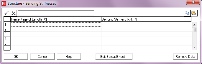
Percentage of Length: |
The percentage of the structure length. This input, coupled with Bending Stiffness, is used to specify a bending stiffness distribution over the structure length. Units: [%] |
Bending Stiffness: |
The bending stiffness of the structure. This input, coupled with Percentage of Length, is used to specify a bending stiffness distribution over the structure length. Units: [kNm2] or [kips.ft2] |
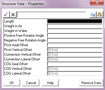
Input |
Description |
Length: |
The length of the yoke. Units: [m] or [ft] |
Weight in Air: |
The weight in air of the yoke. Units: [kN] or [kips] |
Weight in Water: |
The weight in water of the yoke. Units: [kN] or [kips] |
Positive Free Rotation Angle: |
The free rotation angle for the yoke hinge, measured clockwise from an axis perpendicular to the structure length in the plane of the pipeline. Units: [deg] |
Negative Free Rotation Angle: |
The free rotation angle for the yoke hinge, measured anticlockwise from an axis perpendicular to the structure length in the plane of the pipeline. Units: [deg] |
Pivot Axial Offset: |
The distance along the structure centreline from its start point to the point where the yoke hinge is connected to the structure. By default, this input is left blank. Units: [m] or [ft] |
Pivot Vertical Offset: |
The in-plane displacement of the yoke hinge with respect to the structure centreline (that is, the perpendicular distance from the structure centreline to the hinge as measured in elevation view). This defaults to 0. See Note (c). Units: [m] or [ft] |
Connection Vertical Offset: |
The in-plane displacement of the yoke connection point with respect to the yoke centreline (that is, the perpendicular distance from the yoke centreline to the attached cable or line as measured in elevation view). This defaults to 0. See Note (d). Units: [m] or [ft] |
Connection Lateral Offset: |
The horizontal distance between the yoke centreline and the yoke connection node as measured in side view (out-of-plane displacement). This defaults to 0. See Note (d). Units: [m] or [ft] |
COG Axial Offset |
The distance along the yoke centreline from its start point to the point where the centre of gravity element connects to the yoke. By default, this input is left blank in which case the yoke weight is uniformly distributed along its length. Units: [m] or [ft] |
COG Vertical Offset: |
The in-plane displacement of the centre of gravity node with respect to the yoke centreline (that is, the perpendicular distance from the yoke centreline to the free end of the centre of gravity element as measured in elevation view). This defaults to 0. See Note (e). Units: [m] or [ft] |
COG Lateral Offset: |
The horizontal distance between the yoke centreline and the centre of gravity node as measured in side view (that is, the out-of-plane displacement for the centre of gravity node). This defaults to 0. See Note (f). Units: [m] or [ft] |
Notes:
(a)The yoke is modelled as a beam element of high stiffness with a hinge at the structure end. The free rotation angle is defined in terms of positive and negative rotations about an axis perpendicular to the structure, accommodating non-symmetrical free rotational boundaries. While the angle between the yoke and structure is within the user specified free rotation angle, the yoke hinge is free to rotate. Outside this range, the rotation of the hinge is restricted by a high rotational resistance.
(b)A one-dimensional hinge models the connection between the yoke and the structure. The motion of the yoke is limited by the structure frame such that it is constrained to hinge within a limited angular displacement denoted 'Free Rotation Angle' in the figure below.
(c)The Pivot Vertical Offset follows the same sign convention as the structure COG Vertical Offset.
(d)The Connection Vertical Offset and Connection Lateral Offset follow the same sign convention as that of the yoke centre of gravity offsets.
(e)Given that the yoke and its attachments are generally orientated vertically the sign convention for the yoke COG Vertical Offset is different to that of the structure. If the line or cable attached to the yoke has a start point with a smaller global X coordinate than the end point then a positive yoke COG Vertical Offset will place the COG node on the left of the yoke centreline (as measured in elevation view).
(f)The yoke COG Lateral Offset follows the same convention as the corresponding structure input.

Structure-Cable Intersection
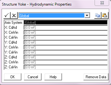
Input |
Description |
Axis System: |
This drop-down list is used to select the axis system in which the hydrodynamic coefficients are defined. The options are Global (the default) and Local. The hydrodynamic coefficients can be specified in the global axis system or in an axis system that is local to the yoke. In the latter case, the local x-axis of each element is used for the tangential force calculations, and the local y- and z-axes are used for the hydrodynamic forces normal to the yoke. Coefficients specified in either axis system account for changes in the orientation of the yoke as it displaces and rotates in space. Note that specification of yoke hydrodynamic properties is optional. By default, yoke hydrodynamics will be omitted. |
X: CdAd: |
The product of the yoke frontal area and drag coefficient in the X direction. Units: [m2] or [ft2] |
X: CmVin: |
The product of the yoke reference volume and inertia coefficient in the X direction. Units: [m3] or [ft3] |
X: CaVin: |
The product of the yoke reference volume and added mass coefficient in the X direction. Units: [m3] or [ft3] |
Y: CdAd: |
The product of the yoke frontal area and drag coefficient in the Y direction. Units: [m2] or [ft2] |
Y: CmVin: |
The product of the yoke reference volume and inertia coefficient in the Y direction. Units: [m3] or [ft3] |
Y: CaVin: |
The product of the yoke reference volume and added mass coefficient in the Y direction. Units: [m3] or [ft3] |
Z: CdAd: |
The product of the yoke frontal area and drag coefficient in the Z direction. Units: [m2] or [ft2] |
Z: CmVin: |
The product of the yoke reference volume and inertia coefficient in the Z direction. Units: [m3] or [ft3] |
Z: CaVin: |
The product of the yoke reference volume and added mass coefficient in the Z direction. Units: [m3] or [ft3] |