Seabed Data Inputs |


|
Seabed Data Inputs |
|
Input |
Description |
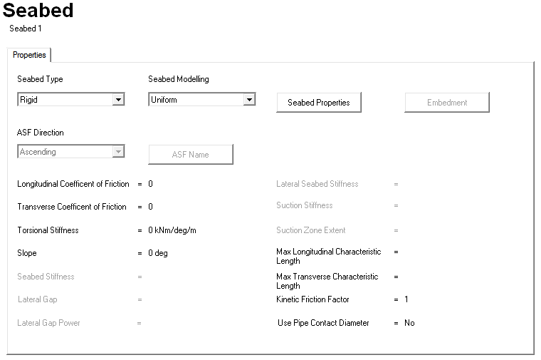
Seabed Type: |
A drop-down list that allows you to specify the seabed type. The options are Rigid (the default) and Elastic. |
Seabed Modelling: |
A drop-down list that allows you to specify whether the seabed is modelled as a uniform or arbitrary surface. |
Seabed Properties |
Click on this button to display a dialog that allows you to enter the properties of the seabed. The dialog that is displayed varies depending on the options that you select in the Seabed Type and Seabed Modelling drop-down lists. See the next four sections of this article, from ‘Rigid Seabed Dialog’, to ‘Arbitrary Elastic Seabed Dialog’ for more information. |
Embedment |
Click on this button to display a dialog that allows you to enter the embedment properties of a non-linear elastic seabed. See the ‘Embedment Dialog’ section for more information. |
ASF Direction: |
A drop-down list that allows you to specify the format of the arbitrary surface file data. This drop-down list is only available if you select Arbitrary from the Seabed Modelling drop-down list. See the ‘Using Arbitrary Surface Files (ASFs)’ section for more information about this option. |
ASF Name |
This button is only available if you select Arbitrary from the Seabed Modelling drop-down list. See the ‘Using Arbitrary Surface Files (ASFs)’ section for information about how to use this option. |
Input |
Description |
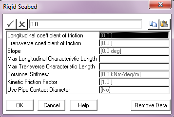
Longitudinal Coefficient of Friction: |
The coefficient of friction between the structure and the seabed in the longitudinal (or axial) direction. This defaults to a value of 0. |
Transverse Coefficient of Friction: |
The coefficient of friction between the structure and the seabed in the transverse direction. This defaults to a value of 0. |
Slope: |
The angle of seabed slope measured anti-clockwise from the global Y-axis. This parameter defaults to 0°. PipeLay models a sloping seabed as passing through the global origin and sloping uniformly in the global XY plane. In other words, the seabed elevation does not vary in the global Z direction. The angle of seabed slope is measured anti-clockwise from the global Y-axis, so that a positive seabed slope means that the seabed elevation increases with increasing distance in the global Y direction. Units: [deg] |
Max Longitudinal Characteristic Length: |
The maximum length to be used in determining the non-linear stiffness used to simulate frictional restraint on the seabed in the longitudinal direction. This input is optional. The Max Longitudinal Characteristic Length and Max Transverse Characteristic Length inputs relate to the operation of the PipeLay seabed friction model, and allow you control over the characteristics of the non-linear springs used to model seabed frictional restraint. These inputs are optional and default to 3.048m or 10ft. These default values are optimum for the vast majority of analyses, and these inputs will be only rarely used. Units: [m] or [ft] |
Max Transverse Characteristic Length: |
The maximum length to be used in determining the non-linear stiffness used to simulate frictional restraint on the seabed in the transverse direction. This input is optional. See the description above for Max Longitudinal Characteristic Length for more information. Units: [m] or [ft] |
Torsional Stiffness: |
The resistance to torsional movement provided by the seabed per unit length. By default, no torsional resistance is modelled. Units: [kNm/deg/m] or [kips.ft/deg/ft] |
Kinetic Friction Factor: |
The ratio between static friction and dynamic friction. The kinetic friction coefficient is typically less than the coefficient of static friction, reflecting the common experience that it is easier to keep an object in motion across a surface than to start the object in motion from rest. So once the pipeline starts to move on the seabed, a kinetic friction coefficient is calculated as follows and is applied to the analysis: kinetic friction coefficient = kinetic friction factor * static friction The kinetic friction factor defaults to 1, which specifies that the same friction coefficient is used regardless of whether or not the pipe is moving. |
Use Pipe Contact Diameter: |
A drop-down list that allows you to specify whether the pipe will contact the seabed when the outer pipe surface touches the seabed (Yes) or when the pipe centreline touches the seabed (No), which is the default legacy approach. |
Input |
Description |
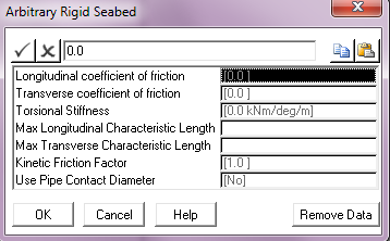
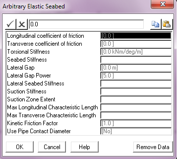
Longitudinal Coefficient of Friction: |
The coefficient of friction between the structure and the seabed in the longitudinal (or axial) direction. This defaults to a value of 0. |
Transverse Coefficient of Friction: |
The coefficient of friction between the structure and the seabed in the transverse direction. This defaults to a value of 0. |
Torsional Stiffness: |
The resistance to torsional movement provided by the seabed per unit length. By default, no torsional resistance is modelled. Units: [kNm/deg/m] or [kips.ft/deg/ft] |
Max Longitudinal Characteristic Length: |
The maximum length to be used in determining the non-linear stiffness used to simulate frictional restraint on the seabed in the longitudinal direction. This input is optional. The Max Longitudinal Characteristic Length and Max Transverse Characteristic Length inputs relate to the operation of the PipeLay seabed friction model, and allow you control over the characteristics of the non-linear springs used to model seabed frictional restraint. These inputs are optional and default to 3.048m or 10ft. These default values are optimum for the vast majority of analyses, and these inputs will be only rarely used. Units: [m] or [ft] |
Max Transverse Characteristic Length: |
The maximum length to be used in determining the non-linear stiffness used to simulate frictional restraint on the seabed in the transverse direction. This input is optional. See the description above for Max Longitudinal Characteristic Length for more information. Units: [m] or [ft] |
Kinetic Friction Factor |
The ratio between static friction and dynamic friction. The kinetic friction coefficient is typically less than the coefficient of static friction, reflecting the common experience that it is easier to keep an object in motion across a surface than to start the object in motion from rest. So once the pipeline starts to move on the seabed, a kinetic friction coefficient is calculated as follows and is applied to the analysis: kinetic friction coefficient = kinetic friction factor * static friction The kinetic friction factor defaults to 1, which specifies that the same friction coefficient is used regardless of whether or not the pipe is moving. |
Use Pipe Contact Diameter: |
A drop-down list that allows you to specify whether the pipe will contact the seabed when the outer pipe surface touches the seabed (Yes) or when the pipe centreline touches the seabed (No), which is the default legacy approach. |
Input |
Description |
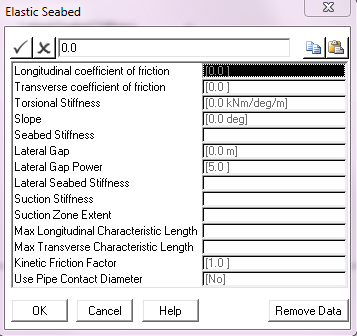
Longitudinal Coefficient of Friction: |
The coefficient of friction between the structure and the seabed in the longitudinal (or axial) direction. This defaults to a value of 0. |
Transverse Coefficient of Friction: |
The coefficient of friction between the structure and the seabed in the transverse direction. This defaults to a value of 0. |
Torsional Stiffness: |
The resistance to torsional movement of the structure provided by the seabed per unit length of the structure. By default, no torsional resistance is modelled. Units: [kNm/deg/m] or [kips.ft/deg/ft] |
Slope: |
The angle of seabed slope measured anti-clockwise from the global Y-axis. This parameter is only relevant for a uniform seabed and defaults to 0°. PipeLay models a sloping seabed as passing through the global origin and sloping uniformly in the global XY plane. In other words, the seabed elevation does not vary in the global Z direction. The angle of seabed slope is measured anti-clockwise from the global Y-axis, so that a positive seabed slope means that the seabed elevation increases with increasing distance in the global Y direction. Units: [deg] |
Seabed Stiffness: |
The elastic stiffness per unit length of the seabed of a linear elastic seabed. Theoretically, the behaviour of an elastic seabed with an infinitely large stiffness should be identical to that of a corresponding rigid seabed of equal profile. However, the modelling of such an elastic seabed can pose problems due to solution convergence difficulties. Generally though this tends to occur for stiffness values which effectively constitute a rigid seabed. So it is advisable to use the rigid seabed contact algorithm when modelling an elastic seabed of very high stiffness. If your seabed is non-linear, leave this input blank. Instead use the Embedment dialog to define a non-linear embedment curve. Units: [kN/m/m] or [kips/ft/ft] |
Lateral Gap: |
The distance over which the pipe can move relatively freely in the lateral direction before the full lateral stiffness is applied. In the case of trench modelling, this input equates to a uniform gap between the outer surface of the pipe and the trench wall. By default no gap is modelled so the full stiffness is applied without any lateral movement. Units: [m] or [ft] |
Lateral Gap Power: |
The power that governs the power law equation used to ramp up the lateral stiffness to its full value as the lateral gap, or gap between the pipe and trench wall, closes. The greater the power the less resistance the pipe will encounter before closing the gap. Note that a power value of 1 effectively equates to a linear stiffness, or zero gap, condition. Also, while there may be a desire to use a relatively large power value this may introduce solution stability issues and so generally the default value of 5 is deemed sufficiently large. |
Lateral Seabed Stiffness: |
This input allows you to specify a lateral resistance to horizontal motion for the elastic seabed. This defaults to a value of 0. The Lateral Seabed Stiffness input specifies a lateral resistance to horizontal motion on the elastic seabed. The facility is activated by inputting a lateral spring stiffness per unit length, and the resistance this provides is integrated into a seabed stiffness matrix for any pipe section on the mudline in a similar manner to the vertical seabed resistance. Naturally the vertical effect is defined in terms of seabed axes and the lateral in terms of a local axis system, which may vary from pipe section to pipe section. However this is readily handled by PipeLay. The resistance to horizontal motion provided by the lateral spring replaces rather than augments transverse friction. The two effects cannot be combined. If you input a non-zero value for both the lateral seabed stiffness and the transverse friction coefficient, PipeLay outputs a warning and sets the friction coefficient to zero. Note that whichever of these effects is present in an analysis provides lateral resistance to pipe sections on the seabed only, and not to pipe sections in the suction zone. Also, the behaviour of the lateral stiffness, meaning whether it is linear or non-linear, is controlled by the Lateral Gap and Lateral Gap Power inputs. Units: [kN/m/m] or [kips/ft/ft] |
Suction Stiffness: |
This input allows you to input a seabed stiffness for pipe sections which have moved off an elastic seabed but which are still in a so called “suction zone” between the mudline and the elevation at which suction forces disappear. Suction Stiffness defaults to a value of 0. The suction or restraining force experienced by a riser pipe section in a “suction zone” just above the mudline is modelled with a linear spring resistance similar to that provided against downward vertical motion by the elastic seabed itself. The suction force is of course directed downwards whereas the seabed resistance is vertically upwards. The inputs for this facility are suction “spring stiffness” per unit length, and the “suction zone extent” which is defined in terms of the elevation above the mudline at which suction forces disappear. The suction force varies linearly between zero at the mudline and the maximum force experienced at the top of the suction zone. Once a pipe section clears the suction zone the suction force returns to zero. One important point about this facility is that suction forces are applied only to pipe sections moving from the mudline into the suction zone. A pipe section moving into the suction zone from above does not experience any force, nor does a pipe section moving upwards through the suction zone unless it has impacted the mudline before ascending. Finally, the specification of suction forces is optional. By default, no suction effects are included in an analysis. Units: [kN/m/m] or [kips/ft/ft] |
Suction Zone Extent: |
This is related to the previous input, Suction Stiffness. Suction Zone Extent represents the elevation or height above the mudline at which suction forces become zero. This input is meaningless unless the soil Suction Stiffness is nonzero, in which case it is a required input. Units: [m] or [ft] |
Max Longitudinal Characteristic Length: |
The maximum length to be used in determining the non-linear stiffness used to simulate frictional restraint on the seabed in the longitudinal direction. This input is optional. The Max Longitudinal Characteristic Length and Max Transverse Characteristic Length inputs relates to the operation of the PipeLay seabed friction model, and allows you control over the characteristics of the non-linear springs used to model seabed frictional restraint. These inputs are optional and default to 3.048m or 10ft. These default values are optimum for the vast majority of analyses, and this input will be only rarely used. Units: [m] or [ft] |
Max Transverse Characteristic Length: |
The maximum length to be used in determining the non-linear stiffness used to simulate frictional restraint on the seabed in the transverse direction. This input is optional. See the description above for Max Longitudinal Characteristic Length for more information. Units: [m] or [ft] |
Kinetic Friction Factor: |
The ratio between static friction and dynamic friction. The kinetic friction coefficient is typically less than the coefficient of static friction, reflecting the common experience that it is easier to keep an object in motion across a surface than to start the object in motion from rest. So once the pipeline starts to move on the seabed, a kinetic friction coefficient is calculated as follows and is applied to the analysis: kinetic friction coefficient = kinetic friction factor * static friction The kinetic friction factor defaults to 1, which specifies that the same friction coefficient is used regardless of whether or not the pipe is moving. |
Use Pipe Contact Diameter: |
A drop-down list that allows you to specify whether the pipe will contact the seabed when the outer pipe surface touches the seabed (Yes) or when the pipe centreline touches the seabed (No), which is the default legacy approach. |
Input |
Description |
Longitudinal Coefficient of Friction: |
The coefficient of friction between the structure and the seabed in the longitudinal (or axial) direction. This defaults to a value of 0. |
Transverse Coefficient of Friction: |
The coefficient of friction between the structure and the seabed in the transverse direction. This defaults to a value of 0. |
Torsional Stiffness: |
The resistance to torsional movement of the structure provided by the seabed per unit length of the structure. By default, no torsional resistance is modelled. Units: [kNm/deg/m] or [kips.ft/deg/ft] |
Seabed Stiffness: |
The elastic stiffness per unit length of the seabed of a linear elastic seabed. Theoretically, the behaviour of an elastic seabed with an infinitely large stiffness should be identical to that of a corresponding rigid seabed of equal profile. However, the modelling of such an elastic seabed can pose problems due to solution convergence difficulties. Generally though this tends to occur for stiffness values which effectively constitute a rigid seabed. So it is advisable to use the rigid seabed contact algorithm when modelling an elastic seabed of very high stiffness. If your seabed is non-linear, leave this input blank. Instead use the Embedment dialog to define a non-linear embedment curve. Units: [kN/m/m] or [kips/ft/ft] |
Lateral Seabed Stiffness: |
This input allows you to specify a lateral resistance to horizontal motion for the elastic seabed. This defaults to a value of 0. The Lateral Seabed Stiffness input specifies a lateral resistance to horizontal motion on the elastic seabed. The facility is activated by inputting a lateral spring stiffness per unit length, and the resistance this provides is integrated into a seabed stiffness matrix for any pipe section on the mudline in a similar manner to the vertical seabed resistance. Naturally one effect is defined in terms of seabed axes and the other in terms of a local axis system, which may vary from pipe section to pipe section. However this is readily handled by PipeLay. The resistance to horizontal motion provided by the lateral spring replaces rather than augments transverse friction. The two effects cannot be combined. If you input a non-zero value for both the lateral seabed stiffness and the transverse friction coefficient, PipeLay outputs a warning and sets the friction coefficient to zero. Note that whichever of these effects is present in an analysis provides lateral resistance to pipe sections on the seabed only, and not to pipe sections in the suction zone. Units: [kN/m/m] or [kips/ft/ft] |
Suction Stiffness: |
This input allows you to input a seabed stiffness for pipe sections which have moved off an elastic seabed but which are still in a so called “suction zone” between the mudline and the elevation at which suction forces disappear. Suction Stiffness defaults to a value of 0. The suction or restraining force experienced by a riser pipe section in a “suction zone” just above the mudline is modelled with a linear spring resistance similar to that provided against downward vertical motion by the elastic seabed itself. The suction force is of course directed downwards whereas the seabed resistance is vertically upwards. The inputs for this facility are suction “spring stiffness” per unit length, and the “suction zone extent” which is defined in terms of the elevation above the mudline at which suction forces disappear. The suction force varies linearly between zero at the mudline and the maximum force experienced at the top of the suction zone. Once a pipe section clears the suction zone the suction force returns to zero. One important point about this facility is that suction forces are applied only to pipe sections moving from the mudline into the suction zone. A pipe section moving into the suction zone from above does not experience any force, nor does a pipe section moving upwards through the suction zone unless it has impacted the mudline before ascending. Finally, the specification of suction forces is optional. By default, no suction effects are included in an analysis. Units: [kN/m/m] or [kips/ft/ft] |
Suction Zone Extent: |
This is related to the previous input, Suction Stiffness. Suction Zone Extent represents the elevation or height above the mudline at which suction forces become zero. This input is meaningless unless the soil Suction Stiffness is nonzero, in which case it is a required input. Units: [m] or [ft] |
Max Longitudinal Characteristic Length: |
The maximum length to be used in determining the non-linear stiffness used to simulate frictional restraint on the seabed in the longitudinal direction. This input is optional. The Max Longitudinal Characteristic Length and Max Transverse Characteristic Length inputs relates to the operation of the PipeLay seabed friction model, and allows you control over the characteristics of the non-linear springs used to model seabed frictional restraint. These inputs are optional and default to 3.048m or 10ft. These default values are optimum for the vast majority of analyses, and this input will be only rarely used. Units: [m] or [ft] |
Max Transverse Characteristic Length: |
The maximum length to be used in determining the non-linear stiffness used to simulate frictional restraint on the seabed in the transverse direction. This input is optional. See the description above for Max Longitudinal Characteristic Length for more information. Units: [m] or [ft] |
Kinetic Friction Factor: |
The ratio between static friction and dynamic friction. The kinetic friction coefficient is typically less than the coefficient of static friction, reflecting the common experience that it is easier to keep an object in motion across a surface than to start the object in motion from rest. So once the pipeline starts to move on the seabed, a kinetic friction coefficient is calculated as follows and is applied to the analysis: kinetic friction coefficient = kinetic friction factor * static friction The kinetic friction factor defaults to 1, which specifies that the same friction coefficient is used regardless of whether or not the pipe is moving. |
Use Pipe Contact Diameter: |
A drop-down list that allows you to specify whether the pipe will contact the seabed when the outer pipe surface touches the seabed (Yes) or when the pipe centreline touches the seabed (No), which is the default legacy approach. |
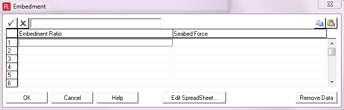
PipeLay provides this dialog to enable you to specify that seabed stiffness varies with the degree of embedment of a riser or pipeline.
Input |
Description |
Embedment Ratio: |
An embedment ratio value on the curve. Embedment ratio in this context is defined as the distance the pipe centreline lies below the seabed, divided by pipe external diameter. So embedment ratio is dimensionless. |
Seabed Force: |
The force exerted by the seabed for this embedment ratio. |
Notes:
(a)This facility operates as follows:
oPipeLay computes the embedment ratio of a pipe lying on the elastic seabed at every iteration during each solution time. Embedment ratio in this context is defined as the distance the pipe centreline lies below the seabed, divided by pipe external diameter. So embedment ratio is dimensionless.
oUsing the embedment curve for the pipe that you specify here, the tangent stiffness of the curve at that embedment is calculated.
oThis value is used as the vertical seabed stiffness for the pipe.
(b)The points defining the force/embedment curve may be specified in any order. PipeLay subsequently sorts the data pairs into ascending order of embedment ratio.
(c)If the computed embedment ratio lies between the specified force/embedment data points that you specify, PipeLay uses linear interpolation to determine the seabed force.
(d)If the computed embedment ratio lies outside the specified range of the force/embedment curve, then PipeLay assumes:
oFor embedment ratios greater than the range of the curve, the tangent stiffness is equal to the tangent stiffness between the final two points defined on the curve.
oFor embedment ratios less than the range of the curve, the tangent stiffness is equal to the tangent stiffness between the first two points defined on the curve.
(e)The use of this dialog and the specification of a linear elastic seabed stiffness are mutually exclusive. Your seabed must be linear or non-linear, it cannot be both.
When you click on the ASF Name button, a dialog is displayed prompting you to select an ASCII data file that contains the profile of an arbitrary surface file. For the most general case, PipeLay allows you to define a two-dimensional rigid surface profile or bathymetry, by specifying an ASCII data file using the Arbitrary Surface File input. This file contains information on the profile of the rigid surface.
The profile of the arbitrary rigid surface varies in the global XY plane and is constant in the global Z direction. See the figure below. The profile is defined by a series of pairs of values, and this is the data that is contained in the ASCII data file. Each line in the file defines a point on the profile and contains data in the format Y-coordinate, Seabed Elevation. Here Y-coordinate is self-explanatory, and Seabed Elevation is the height of the seabed at this point above the datum X=0. Linear interpolation is used to determine the rigid surface profile between user-specified points, while outside the range of points the surface is assumed to be flat and horizontal.

Definition of Arbitrary Profile Rigid Surface
Two data values are necessary to define the profile shown above, namely the values for Points (1) and (2). The arbitrary surface file for this example would look like this:
100.0, 30.0
0.0, 0.0
The first line of data defines Point (1) and the second line defines point (2). Point 1 is a distance of 100 (units) along the positive Y-axis, and the seabed at that point is 30 units above X=0. The seabed slopes uniformly from Point (1) to Point (2). Elsewhere the seabed is flat.
ASF Direction
In the previous discussion, the contents of the arbitrary surface file are described in terms of two values - Y-coordinate and Seabed Elevation. Strictly speaking, Seabed Elevation is not a fully accurate description. What Seabed Elevation means depends on the ASF Direction you have defined. For the default of Ascending, Seabed Elevation is the height of the seabed at this point above the datum X=0. For the case of Descending, Seabed Elevation is the distance to the seabed at this point from the Mean Water Line.