Dynamic Display - Menu Bar Reference |


|
Dynamic Display - Menu Bar Reference |
|
There are eight menus in the Dynamic Display module menu bar. These are File, Edit, View, Options, Animate, Orientation, Window and Help.
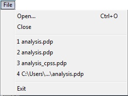
The File menu contains the commands Open, Close, and Exit, and a list of recently used files. All of these commands work in the standard manner for Windows® applications. As stated earlier, Dynamic Display animation files have the extension ‘.pdp’.
The Edit menu contains one item, Copy. The copy command allows the user to copy the active view into memory. The image can then be pasted into applications such as Microsoft Word.
![]()
The View menu contains two items: Standard Toolbar and View Toolbar.
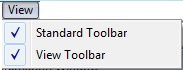
These two options enable or disable the display of the toolbars. The toolbars are described later in the ‘Toolbar Reference’ article.
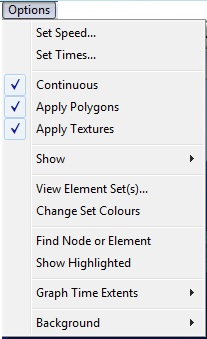
The menu you get when you select Options from the top menu bar is shown below. Most of options on this menu relate to the display of animation views. With the exception of the Set Times option, all of the options are saved when you exit the Dynamic Display module and restored when you restart it. Each of the options is described below.
The first command on the Options menu is Set Speed. The following window appears when this option is invoked:
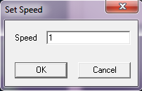
The animation display speed is a multiple of the actual speed of the simulation time; you may enter any positive number. A display speed of 1 corresponds to real time, which means that 1 second of simulation time is displayed in 1 second of real time. The default speed of 5 means the animation is displayed at 5 times the actual speed, that is, 5 seconds of simulation time is displayed in 1 second of real time. PipeLay automatically relates real time and animation speed using the computer clock, so that the animation speed is machine-independent. If necessary, it skips some animation frames to maintain the correct speed. Consequently, if you set the speed too high for your computer’s performance, animations may appear ‘jumpy’.
The Set Times command is used to specify the animation start and end times. Selecting this command displays the window shown below.
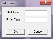
PipeLay scans the current animation file for the analysis start and end times and displays them as the default Start Time and Finish Time, respectively. You cannot specify times that are less than the default start or greater than the default end.
This option can be used to specify whether the animation is to start again when the end is reached. The alternative is that the animation terminates as soon as the animation end time is reached.
A PipeLay animation can show the structure with just lines, or draw polygon cylinders around each element of the structure. The cylinder diameters correspond to the outer diameters of sections. This menu item toggles this facility on/off.
This option allows you to enable or disable texture mapping. When the option is enabled, textures are mapped onto the seabed and wave surface, providing a greater sense of realism. Also, when Apply Polygons is enabled, a texture is mapped onto each polygon cylinder and panel.
When you select Show on the Options menu, the following sub-menu appears:
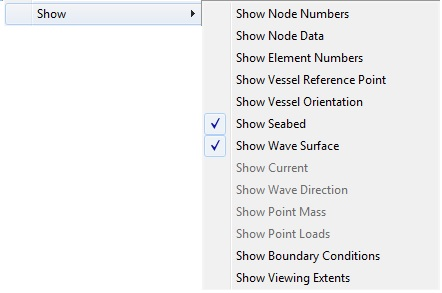
Some of these options may be disabled if the dynamic display file (.pdp) you are viewing does not contain a particular piece of information.
The Show Node Numbers option displays the node numbers on the structure. This can be a useful option when using the Geometry Preview facility in the Analysis module. A section of riser with the node numbers shown is presented below.

The Show Node Data option displays the X, Y and Z coordinate of every node in the model. This can be useful when viewing an incomplete model with the Geometry Preview facility. The figure below shows the same section of riser as that presented before, this time with the node data displayed instead.

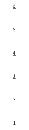
The Show Element Number option toggles the display of element numbers. Element numbers are underlined to distinguish them from node numbers. Below, the same section of riser as in the previous two figures is again shown. In this final case, the element numbers are being shown.
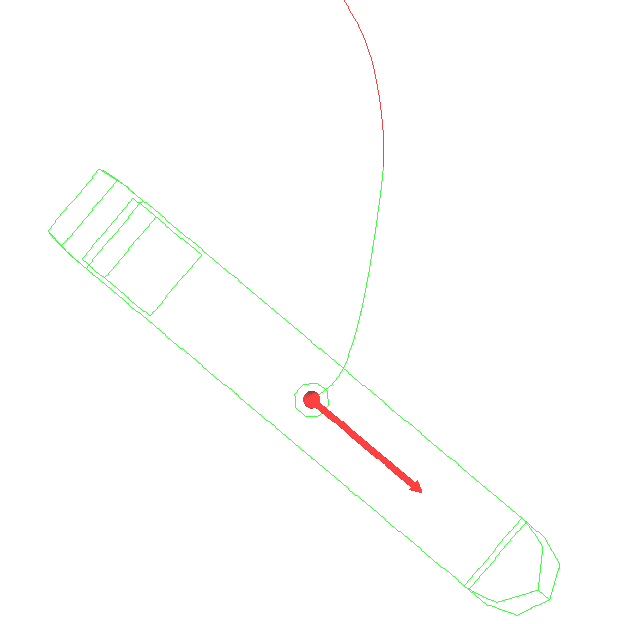
The Show Vessel Reference Point option allows you to display a red circle indicating the instantaneous location of the reference point of vessels in an analysis.
The instantaneous orientation of vessels in an analysis can be displayed by means of an arrow located at the instantaneous location of the corresponding vessel reference points. The Show Vessel Orientation option can be used to toggle this display on or off.
The figure below shows a plan view of a vessel and riser. The symbol indicating the vessel reference point and the arrow indicating the vessel orientation can be clearly seen.
The Show Seabed and Show Wave Surface options display or hide the seabed and wave surface respectively.
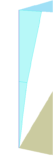
The Show Current option plots the current profile from the seabed to the water surface. If the dynamic display file does not contain information about the current, this option is disabled. The figure below shows a piecewise linear current as represented by the Dynamic Display.
The Show Wave Direction option, when selected, draws an arrow from one corner of the wave surface, indicating the wave direction, as shown below.

The Show Point Mass option places cubes, centred at the respective nodes, to indicate where point masses are located. The figure below shows the symbol for point mass over a riser node.
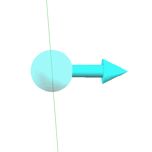
Point loads can be seen with the Show Point Loads options. For translational degrees of freedom a transparent sphere with an arrow in the direction of the load is drawn. A point load is shown below.
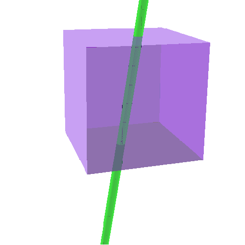
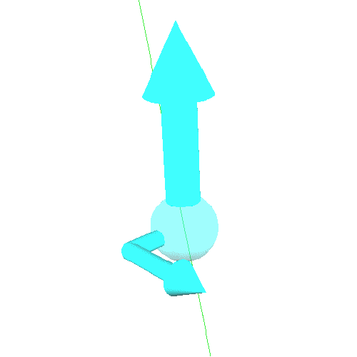
For rotational degrees of freedom, a large arrow indicates the axis of rotation. A transparent sphere and a small arrow are drawn perpendicular to the axis. The smaller arrow indicates the direction of point moment about the axis. The figure below shows a point moment symbol.
To view boundary conditions, the Show Boundary Conditions option may be used. Transparent pyramids are drawn over nodes where boundary conditions have been applied when this option is selected. The figure below shows a node with its boundary condition symbol.

The final option on the Show menu is Show Viewing Extents. This shows the current extents for the model, as shown in the figure below.

The View Element Set(s) option provides the capability to view particular element sets rather than a full model. For example, in a complex model this might allow you to focus on a particular area of interest that might otherwise be obscured. When you invoke this option, the window shown below is displayed. The exact contents of the window will depend on your model – naturally the actual set names will reflect the names you used when defining your finite element data.

Initially all element sets are selected. A set is selected for viewing if there is a tick mark in the check box to the left of the set name. You deselect a set by clicking on the check box with the left mouse button. When you do this, the check box will be empty and the Dynamic Display will not include the elements of the corresponding set.
As you might notice in the above window, there is a set added to the list of user-defined sets called Auxiliary Elements. This set is created internally by the Dynamic Display module and allows you to switch on or off a vessel profile in a model. Auxiliary elements are not included in any set you define for inputting geometric properties, so without this option there would be no way to remove these elements from an animation.
The Change Set Colours option allows the user to change the default colours assigned to each set. Every time the option is selected, the set colours will be offset by one.
The Find Node or Element option displays the window shown below, and allows you to locate any node or element in the model. You simply enter the node or element number in the slot provided, and then click on either Find Node or Find Element as appropriate. If found, the node or element number is displayed on the model. There is also an option to display a specified number of adjacent nodes/elements to the one just found. This is done by entering the number of nodes/elements to be displayed in the slot ‘Number of nodes/elements to display. The displayed node(s)/element(s) can then be toggled on or off using the Show Highlighted option discussed below.

The Show Highlighted option works with the Find Node or Element option, described above. When the Find Node or Element option has located a specified node or element, the location and node or element number are displayed on the model. The Show Highlighted option can then be used to toggle this display on or off.
When you select Background on the Options menu, the following options are presented:
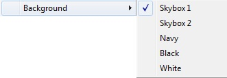
These allow you to toggle the background between two 3D backgrounds and three flat background colours (Navy, Black and White). See the DirectX Features section for more information about the 3D backgrounds.
Note: The white background option is useful if you want to insert a “screen grab” from the dynamic display into a report. With a white background the image is clearer and easy to interpret, the size of the image can be reduced, and printing the image may be much faster.
The Animate menu, which is shown below, contains five options, Play, Pause, Frame by Frame, Rewind and Fast Forward. To start playing an animation, you simply select Play. When you do this, the animation begins, the Pause option becomes enabled, and the Play option is itself disabled.
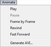
Likewise, to pause an animation that is running, simply select Pause from the menu. When you do this, Play becomes enabled and Pause becomes disabled.
While an animation is suspended, you can resume in Frame by Frame play mode using the third option in the menu above. The animation plays forward one step at a time. Rewind allows you to go directly back to the beginning of an animation. Fast Forward on the other hand jumps directly to the end of an animation.
The final option on the menu is Generate AVI…. As the name implies, this option allows you to create a Windows® standard video file containing your animation. This file can be easily shared with non-PipeLay users. This feature is quite extensive and is described later in more detail in the article ‘Generating AVIs’.
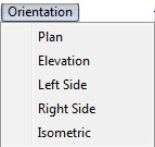
The Orientation menu contains five items, Plan, Elevation, Left Side, Right Side and Isometric. When you select one of these items, the orientation of the structure view in the active animation window changes.
The Window menu shown below contains commands for creating, destroying and controlling windows. The first one, New Animation, will create a new animation window. This window can be used to zoom in on one particular part of the structure or to simply view the structure from a different viewpoint.
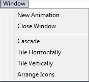
The next Window menu command is Close Window. This will simply close the currently selected window. Any window closed can be reopened later using the New Animation command already discussed.
The last four commands — Cascade, Tile Horizontally, Tile Vertically and Arrange Icons — are standard functions common to many Window applications. They allow you to rearrange the layout of all of the windows that are currently open.
The last menu, Help, is shown below. It has just one command, About, which displays the Dynamic Display module’s About Box.
![]()